
Coarse and fine layered, fast and slow combined and active and passive integrated multi-level composite control method for spacecraft

A composite control and spacecraft technology, applied in attitude control, aerospace vehicles, aircraft and other directions, can solve the problem that the load pointing accuracy and stability cannot be further improved, the optical load cannot further improve the imaging quality, and the accuracy cannot achieve flexible vibration. and high-frequency micro-vibration active control

Active Publication Date: 2018-12-14
BEIJING INST OF CONTROL ENG
View PDF8 Cites 12 Cited by
  • Summary
  • Abstract
  • Description
  • Claims
  • Application Information

AI Technical Summary

Problems solved by technology

The flexible vibration and high-frequency micro-vibration existing in the spacecraft star are directly transmitted to the payload, so that the optical payload cannot further improve the imaging quality
However, the traditional spacecraft attitude system is limited by the bandwidth of the controller and the accuracy of the actuator, so it cannot realize the active control of the flexible vibration and high-frequency micro-vibration, and the further improvement of the control accuracy and stability of the star is limited.
[0006] 2. It is difficult to achieve ultra-high precision pointing and ultra-high stability control of the load optical axis
Limited by factors such as the measurement bandwidth of the sensor and the response bandwidth of the actuator, the pointing accuracy and stability of the load cannot be further improved

Method used


Image

  • Coarse and fine layered, fast and slow combined and active and passive integrated multi-level composite control method for spacecraft
  • Coarse and fine layered, fast and slow combined and active and passive integrated multi-level composite control method for spacecraft
  • Coarse and fine layered, fast and slow combined and active and passive integrated multi-level composite control method for spacecraft

Examples


Embodiment Construction

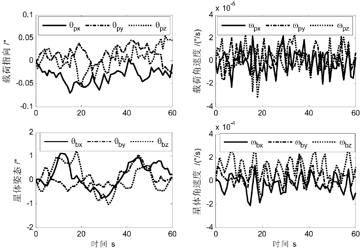
[0064] The present invention adopts figure 1 The process shown in the figure completes a multi-level compound control method of combining coarse and fine layering speed of the spacecraft with the integration of main and passive parts: the specific method is as follows:

[0065] (1) The multi-level composite control system of the spacecraft mainly includes the star platform, the active pointing ultra-static platform, the payload, and the fast mirror. The astral platform is used to support the active pointing ultra-static platform and the load; the active pointing ultra-static platform is installed between the load and the astral platform. The payload is an optical system for high-quality imaging of the target celestial body; the fast mirror is installed inside the payload to adjust the pointing method of the payload's optical axis. The sensors in the spacecraft multi-level compound control system include: star gyroscope, load micrometer sensor, load star sensor, active pointin...


PUM


Abstract

The invention relates to a coarse and fine layered, fast and slow combined and active and passive integrated multi-level composite control method for a spacecraft. A layered control idea in a star-load-fast reflection mirror three-level system includes the following steps: 1) fast reflection mirror third-level control: adopting a guiding star sensor as a measuring component, adopting a fast reflection mirror actuator as an executing mechanism, and adopting a PID controller to realize the ultra-high-precision pointing control of a rolling-pitching axis of a fast reflection mirror; 2) load secondary control: adopting a load star sensor, a micrometer gyroscope and an FSM eddy current as the measuring components, adopting an active pointing ultra-static platform (VIPPS) actuator as the executing mechanism, and adopting the PID controller to realize the high-precision pointing control of the load; and 3) star first-level control: adopting a gyroscope, the load star sensor and a VIPPS eddy current as the measuring components, adopting a momentum wheel as the executing mechanism, and adopting the PID controller to realize the coarse pointing control of the star.

Description

technical field [0001] The invention belongs to the field of spacecraft attitude control, and relates to a three-stage attitude control system and a control method for realizing a star body-load-fast mirror of a spacecraft. Background technique [0002] At present, spacecraft generally use components containing high-speed rotors such as flywheels and control moment gyroscopes as actuators for attitude control systems. These high-speed rotating parts will inevitably produce high-frequency jitter and micro-vibration, which directly affect the working performance of the load. This cannot meet the requirements of space missions such as astronomical observations and extremely high-resolution earth observations that require high-performance control of optical loads. The spacecraft multi-level compound control system was born to meet the demand for high-precision attitude control of this type of optical load. The spacecraft multi-level composite control system refers to the space...

Claims


Application Information

Patent Timeline
IPC IPC(8): G05D1/08
CPCB64G1/244
Inventor 汤亮关新王有懿张科备郝仁剑
Owner BEIJING INST OF CONTROL ENG
Learn More