Flow regulating valve

A flow regulating valve, flow regulating technology, applied in the direction of valve lifting, valve energy absorption device, valve details, etc., can solve the problems of reducing the service life of the valve, inaccurate flow regulation, large flow fluctuations, etc., to improve the use of The effect of long life, accurate flow regulation and small flow fluctuation

Active Publication Date: 2015-09-23
SHANDONG BOAO POWER EQUIP CO LTD
View PDF5 Cites 6 Cited by
  • Summary
  • Abstract
  • Description
  • Claims
  • Application Information

AI Technical Summary

Problems solved by technology

[0004] The disadvantages of the above-mentioned flow regulating valves are that, when adjusting in a small amount, it is easy to appear the phenomenon of "micro-opening and flushing damage", which greatly reduces the service life of the valve
When the valve inlet pressure is constant, the smaller the opening of the valve core, the greater the scouring force on the sealing surface of the valve core and valve seat. If the valve core is in a small opening for a long time, the The sealing surface will be damaged; the second is that the flow adjustment is inaccurate when adjusting the flow, the flow fluctuates greatly and generates large noise

Method used


Image

  • Flow regulating valve
  • Flow regulating valve
  • Flow regulating valve

Examples


Embodiment Construction

[0019] Below in conjunction with embodiment, the present invention is further described:

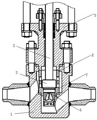
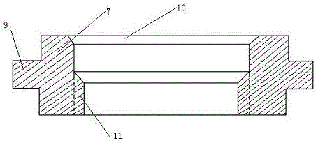
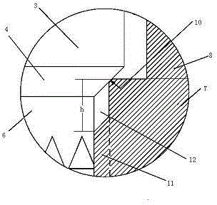
[0020] As shown in the figure: A flow regulating valve is provided with a valve body. The valve body 1 is provided with a cylindrical valve seat hole. The valve body 1 is provided with a liquid inlet cavity and a liquid outlet cavity connected through the valve seat hole. The liquid cavity and the liquid outlet cavity are respectively connected with the liquid inlet and the liquid outlet through the valve body channel, the valve seat hole is provided with a cylindrical valve seat matched with the valve seat hole, and the cylindrical valve seat is provided with a valve stem 2 The lower end of the valve stem 2 is provided with a valve core 3, the periphery of the lower end surface of the valve core 3 is provided with a conical frustum-shaped valve core sealing surface 4 that is inclined to the valve stem axis, and the inner wall of the lower part of the cylindrical valve seat is provided wi...


PUM


Abstract

The invention discloses a flow regulating valve which is characterized in that a barrel-shaped guide sleeve is arranged at the lower end of a valve core; flow adjusting windows are formed in the barrel-shaped guide sleeve and composed of a triangular window and a rectangular window; the upper layer is the triangular window with an upward vertex angle; a barrel-shaped valve seat is composed of a valve seat and a valve barrel; the inner diameter of the valve seat is smaller than that of the valve barrel; an assembly boss is arranged in the middle of the outer wall of the valve seat; an assembly groove matched with the lower end part of the assembly boss of the valve seat is formed at a liquid outlet in a valve body; the valve seat is connected with the valve body through the assembly boss and the assembly groove; an assembly groove matched with the upper end part of the assembly boss of the valve seat is formed in the inner wall of the lower end of the valve barrel; the valve barrel is connected with the valve seat through the assembly groove and the assembly boss; and the valve barrel and the valve seat are fixed in the valve body through a valve cover and bolts. According to the flow regulating valve, cut-off sealing surfaces of the valve core and the valve seat are separated from a flow adjusting surface, so that the phenomenon that the valve is damaged due to washing when being opened slightly is avoided, therefore, the service life of the valve is prolonged greatly; and the flow regulating valve has the advantages of accurate flow adjustment, small flow fluctuation during starting, low noise and the like.

Description

technical field [0001] The invention relates to valve technology, in particular to a flow regulating valve with simple operation, convenient flow control and long service life. Background technique [0002] As we all know, the flow control valve in the valve is widely used in thermal power systems such as thermal power generation and petrochemical industry, especially in thermal power systems such as thermal power generation and petrochemical industry. There is a cylindrical valve seat hole in the body, a liquid inlet cavity connected with the valve seat hole is arranged under the valve seat hole, and a liquid outlet cavity is arranged on the valve body in the middle of the valve seat hole, and the liquid inlet cavity and the liquid outlet cavity are respectively passed through the valve. The channel in the body is connected with the liquid inlet and the liquid outlet, the valve seat hole is provided with a cylindrical valve seat matched with the valve seat hole, the valve s...

Claims


Application Information

Patent Timeline
Patent Type & Authority Applications(China)
IPC IPC(8): F16K1/00F16K1/52F16K47/02
CPCF16K1/00F16K1/52F16K47/02
Inventor 苗蕴博
Owner SHANDONG BOAO POWER EQUIP CO LTD
Why Eureka
Try Eureka