
A pressurized sealing grate

A technology for sealing grate teeth and grate teeth is applied in the field of rotary sealing devices, which can solve the problems of insufficient sealing air pressure, damage to the performance of the compression system, and reduce the performance of the whole machine, so as to prolong the service life and improve the stability margin. , The effect of improving the performance of the whole machine

Inactive Publication Date: 2016-05-11
CIVIL AVIATION FLIGHT UNIV OF CHINA
View PDF3 Cites 0 Cited by
  • Summary
  • Abstract
  • Description
  • Claims
  • Application Information

AI Technical Summary

Problems solved by technology

However, the sealing air pressure of the bearing chamber sealing system is not enough to seal at the low speed stage when the gas turbine is just started, resulting in oil leakage
At the same time, the higher bleed air volume will also damage the performance of the compression system, thereby reducing the performance of the whole machine

Method used

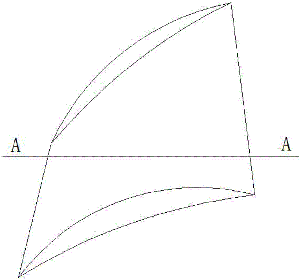

Image

  • A pressurized sealing grate
  • A pressurized sealing grate
  • A pressurized sealing grate

Examples


Embodiment Construction

[0015] The present invention will be further described in detail below in conjunction with the accompanying drawings.

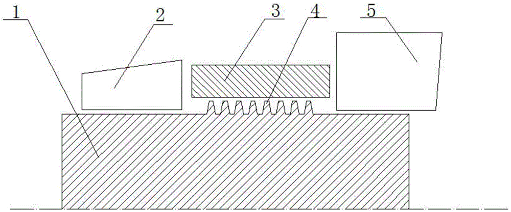
[0016] figure 1 It is a schematic diagram of the structure of sealing grate teeth in traditional technology. Grate teeth 4 are processed on the rotating shaft 1, and together with the stationary ring surface 3, they form a sealing surface to isolate the high-pressure air chamber 2 and the lubricating oil chamber 5.

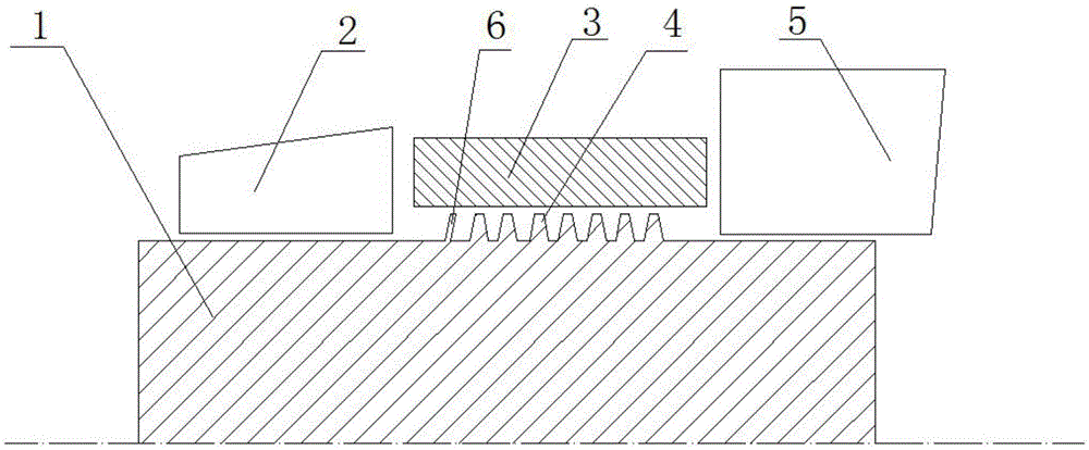
[0017] Such as figure 2 As shown, the present invention provides a pressurized sealing grate structure, including a rotating shaft 1 and a stationary annulus 3. The rotating shaft 1 is provided with a booster vane 6 and a grate tooth 4. The stationary annulus 3 Close to the booster blade 6 and the grate teeth 4 to form a sealing surface.

[0018] If the number of booster blades 6 and grate teeth 4 in this invention is N, then the number of said booster blades 6 can be N-1. The 1st to N-1th in 4 are replaced by booster blades 6; and the blade ...


PUM


Abstract

The invention belongs to rotary sealing devices, and particularly relates to a sealing labyrinth device which is applied to the field of aero-engines, gas turbines and steam turbines. The invention provides a novel supercharged sealing labyrinth which can improve the sealing effect at a low rotating speed stage, and comprises a rotating shaft and a static ring surface. The rotating shaft is provided with supercharging blades and common labyrinth bodies. The static ring surface closely abuts against the supercharging blades and the common labyrinth bodies to form a sealing surface. The novel supercharged sealing labyrinth has the advantages that the sealing effect can be improved at the low rotating speed stage, and meanwhile the demand for the air entraining content is lowered. Accordingly, the engine performance is improved, and the oil consumption rate of an engine is lowered; under the condition that the fuel loading amount is the same, the operational radius of action of an aircraft can be increased, and the temperature of a turbine inlet is lowered; and therefore the service life of a turbine is prolonged, the overhaul period and the scrapping period of the engine are prolonged, and the purpose of lowering the cost is achieved.

Description

technical field [0001] The invention belongs to a rotary sealing device, in particular to a sealing grate device, which is applied to the fields of aero-engines, gas turbines and steam turbines. Background technique [0002] In various industrial installations, the sealing grate has been widely used as an important sealing element, and its sealing performance also greatly affects the performance of the equipment. [0003] Grate seal is an effective and long-life non-contact sealing structure widely used in gas turbines, such as the top of compressor blades and turbine blades, cooling in flow path systems, gas isolation, and bearing cavity lubricating oil sealing systems Oil and gas isolation, etc. Grate seals have a significant impact on the performance, reliability, life and maintenance of gas turbines. Engine failures and accidents often occur due to sealing problems. With the improvement of gas turbine performance, the increase of cycle parameters and the increase of rot...

Claims


Application Information

Patent Timeline
Patent Type & Authority Patents(China)
IPC IPC(8): F01D11/00
Inventor 赵军
Owner CIVIL AVIATION FLIGHT UNIV OF CHINA
Learn More