
A fuel filler pipe assembly

A filling pipe and fuel oil technology, applied in the field of vehicle accessories, can solve the problems of small sealing contact surface, high processing cost, complex structure, etc., and achieve the effect of good sealing performance, simple structure and high safety factor

Active Publication Date: 2017-06-13
NINGBO SHUNJIANG AUTO PARTS MFG
View PDF9 Cites 0 Cited by
  • Summary
  • Abstract
  • Description
  • Claims
  • Application Information

AI Technical Summary

Problems solved by technology

In the prior art, the refueling end of the traditional refueling pipe is usually provided with a threaded pipe body that can prevent fuel from overflowing when refueling. The threaded pipe body is generally installed in the refueling pipe by press-fitting. The pipe is fixedly matched and screwed with the fuel tank cap, which leads to its complex structure and high processing cost. At the same time, the traditional fuel filler pipe has a small sealing contact surface with the fuel tank cap, which is easy to cause oil leakage. Therefore, the traditional fuel filler The tube still needs to be further improved

Method used


Image

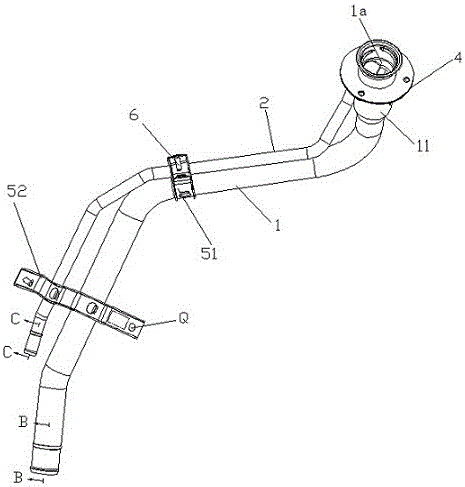
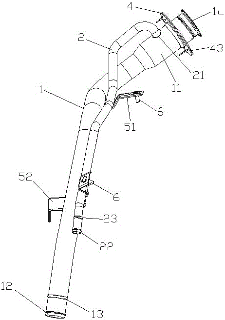
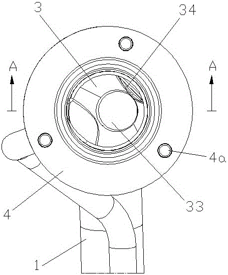
  • A fuel filler pipe assembly
  • A fuel filler pipe assembly
  • A fuel filler pipe assembly

Examples


Embodiment Construction

[0020] Embodiments of the present invention will be further described in detail below in conjunction with the accompanying drawings.

[0021] Figure 1 to Figure 6 It is a structural schematic diagram of the present invention.

[0022] The reference signs are: anti-overflow chamber K, assembly hole Q, oil filling pipe 1, oil filling chamber 1a, inner circular sealing inclined surface 1b, arc surface 1c, internal thread 1d, oil filling end 11, oil outlet connecting convex mouth 12, Refueling pipe annular bead 13, air outlet pipe 2, air outlet end 21, air intake connection convex nozzle 22, air outlet pipe annular bead 23, overflow prevention sleeve 3, round pipe part 31, constriction part 32, round pipe refueling port 33, lock Tightening piece 34, connecting flange assembly 4, bolt hole 4a, stainless steel flange plate 41, anti-off button hole 41a, gasket 42, anti-off positioning button 42a, spot welding nut 43, first bracket 51, second Support 52, spot welding bolt 6.

[00...


PUM


Abstract

The invention discloses a fuel filler pipe assembly, which comprises a fuel filler pipe with a specific space curved direction and an air outlet pipe with a specific spatial curved direction and an air outlet connected to the fuel filler end of the fuel filler pipe. The anti-spill cover to prevent the fuel from spilling when the fuel gun is refueling. The refueling end of the refueling pipe has a refueling cavity that can accommodate the refueling of the refueling gun, which is formed by expanding the diameter of the refueling process. The inner sealing inclined surface of the sealing fit and the arc-shaped surface that can be turned outward in an arc shape can be limitedly matched with the fuel tank cap. The inner wall of the refueling chamber is located below the inner sealing inclined surface and is integrally formed by rolling technology to form a screw connection with the fuel tank cap. The internal thread, the anti-overflow sleeve is fixedly installed in the refueling chamber and is located below the internal thread. The invention has the advantages of simple structure, smooth refueling, good sealing performance and high safety factor, and can meet the refueling demand of the current automobile market.

Description

technical field [0001] The invention relates to the field of vehicle accessories, in particular to a fuel filling pipe assembly used in vehicles to deliver fuel from a fuel gun to a fuel tank. Background technique [0002] With the rapid development of my country's automobile industry and the continuous improvement of people's living standards, the demand for family cars has also increased sharply. Cars are usually fueled with gasoline or diesel oil and are equipped with a fuel tank. In order to facilitate the sealing and refueling of the fuel tank, the filling port of the fuel tank is provided with a special filler pipe. In the prior art, the refueling end of the traditional refueling pipe is usually provided with a threaded pipe body that can prevent fuel from overflowing when refueling. The threaded pipe body is generally installed in the refueling pipe by press-fitting. The pipe is fixedly matched and screwed with the fuel tank cap, which leads to its complex structure ...

Claims


Application Information

Patent Timeline
Patent Type & Authority Patents(China)
IPC IPC(8): B60K15/01B60K15/04
Inventor 姜志明
Owner NINGBO SHUNJIANG AUTO PARTS MFG
Learn More