Thrust washer and torque converter containing the same

A thrust washer and torque converter technology, applied in couplings, clutches, clutches, etc., can solve problems such as failure and torque converter performance degradation, and achieve the effects of slowing down flow, increasing flow, and reducing turbulence.

Inactive Publication Date: 2015-09-16
FCA US
View PDF3 Cites 2 Cited by
  • Summary
  • Abstract
  • Description
  • Claims
  • Application Information

AI Technical Summary

Problems solved by technology

However, once the velocity of the fluid reaches a certain value, a significant build-up of back pressure can occur within the torque converter due to the failure of the fluid to pass between the outer and inner diameters of the thrust washer at a sufficient rate
The build-up of this back pressure can lead to reduced performance and possible failure of the torque converter

Method used


Image

  • Thrust washer and torque converter containing the same
  • Thrust washer and torque converter containing the same
  • Thrust washer and torque converter containing the same

Examples


Embodiment Construction

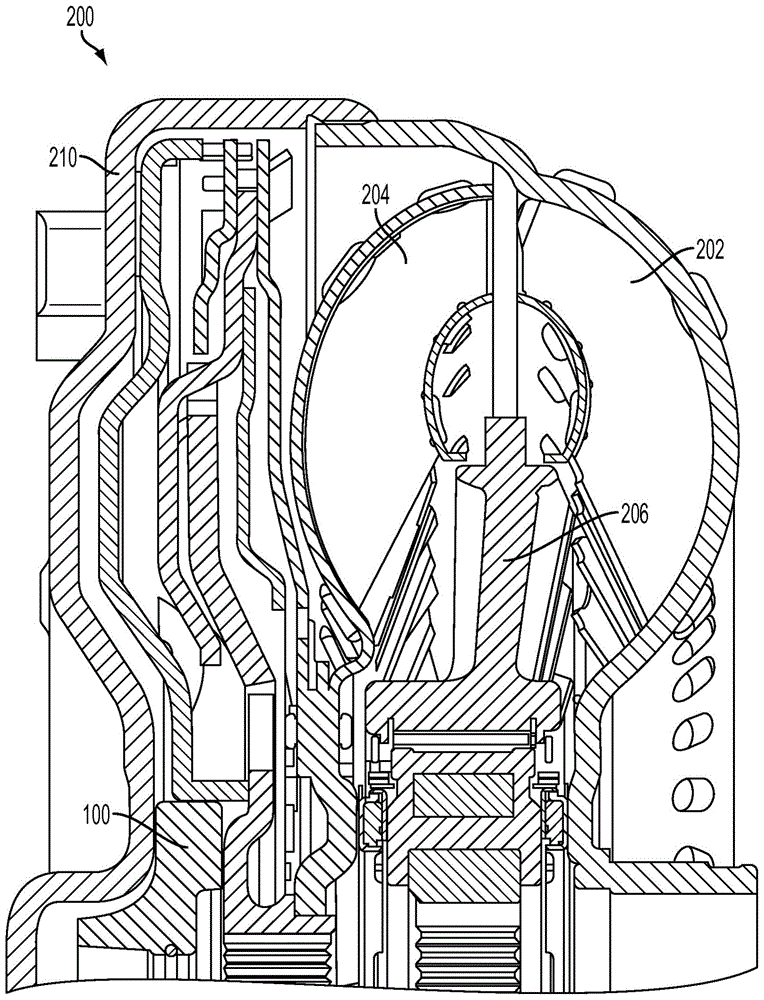
[0022] figure 1 is a cross-sectional view of torque converter 200 showing the locations of thrust washer 100 , impeller 202 , turbine 204 , stator 206 , and cover 210 . Embodiments of the thrust washer contemplated herein provide more desirable fluid flow within the torque converter. During operation of torque converter 200 , torque generated from an engine (not shown) drives impeller 202 . Cover 210 is attached to impeller 202 so both cover 210 and impeller 202 rotate at the same speed as the engine. Turbine 204 is connected to an output shaft (not shown), which, when used in automotive applications, is the input shaft of a transmission (not shown). Turbine 204 and impeller 202 have blades oriented such that as impeller 202 rotates, fluid within torque converter 200 is forced into the blades of turbine 204 , transferring energy to turbine 204 and forcing it to rotate.

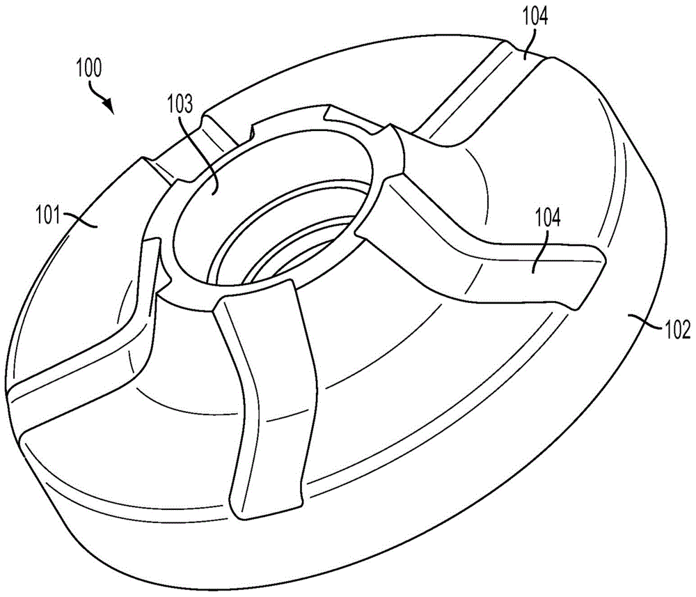
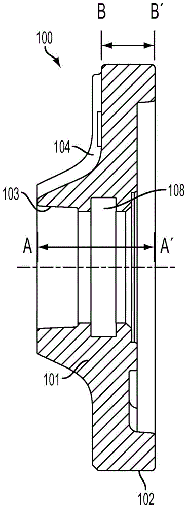
[0023] figure 2 and image 3 A thrust washer 100 according to the present embodiment is shown. A thr...


PUM


Abstract

A thrust washer for a torque converter, the thrust washer having a curved front surface with a plurality of grooves for increasing fluid flow between the inner diameter and the outer diameter of the thrust washer. This increased fluid flow reduces the buildup of back pressure within the torque converter enabling better operation thereof.

Description

technical field [0001] The present disclosure relates to thrust washers for torque converters, and more particularly, the present disclosure relates to thrust washers designed to maximize fluid flow and reduce the build-up of back pressure within the torque converter. Background technique [0002] A torque converter is a fluid-filled component typically used in automatic and powershift transmissions. A torque converter uses fluid to transfer energy from an input (usually an engine) to an output (usually a transmission) and consists of three main components: a turbine, an impeller, and a stator. During operation of the torque converter, the torque produced by the engine drives the impeller. The cover is attached to the impeller so the cover and impeller rotate at the same speed as the engine. The turbine is connected to the output shaft and the stator is connected to the non-rotating support shaft. The turbine and impeller have blades oriented such that as the impeller rot...

Claims


Application Information

Patent Timeline
Patent Type & Authority Applications(China)
IPC IPC(8): F16H41/28F16H41/24F16H45/02F16D33/18
CPCF16H41/24F16H2045/0205
Inventor 迈克尔·芬格门达尔吉特·辛格托马斯·K·基特林斯基约翰·G·拉斯可普拉桑特·莫迪马文·G·席曼威廉·S·黑文
Owner FCA US
Why Eureka
Try Eureka