
Method for increasing stator core slot area, stator core, stator and motor

A technology of stator iron core and stator slot, applied in the direction of magnetic circuit static parts, magnetic circuit shape/style/structure, etc., can solve the problems of heavy motor, high motor material cost, and high motor transportation cost, so as to reduce the overall cost, The effect of improving motor efficiency and increasing slot area

Active Publication Date: 2018-01-16
GUANGDONG WELLING ELECTRIC MACHINE MFG +1
View PDF7 Cites 0 Cited by
  • Summary
  • Abstract
  • Description
  • Claims
  • Application Information

AI Technical Summary

Problems solved by technology

The structural shape of the stator core is unreasonable, which leads to the following disadvantages in the specific application of the motor: 1) The effective slot area of ​​the stator slot is small, so that the number of winding turns of the stator winding is small, and in order to ensure Due to the high efficiency of the motor, the stator winding can only be formed by winding copper wire with a small resistivity, which makes the material cost of the motor higher; 2) The material of the stator core is not fully utilized, making the motor heavier, which in turn makes the The transportation cost of the motor is relatively high

Method used


Image

  • Method for increasing stator core slot area, stator core, stator and motor
  • Method for increasing stator core slot area, stator core, stator and motor
  • Method for increasing stator core slot area, stator core, stator and motor

Examples


Embodiment 1

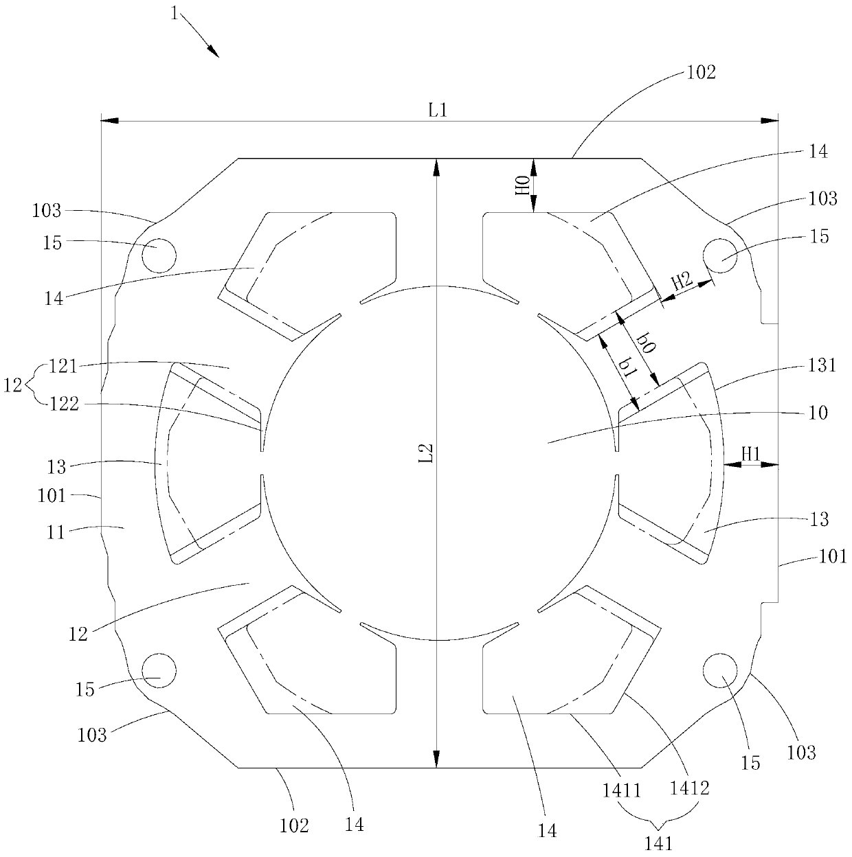
[0023] Such as figure 1 As shown, the method for increasing the slot area of ​​the stator core provided by Embodiment 1 of the present invention is suitable for the outer contour including two opposite first straight outer edges 101, two opposite second straight outer edges 102 and four opposite straight outer edges. A stator core 1 with two corner outer edges 103, wherein, two first straight outer edges 101 are opposite and arranged in parallel, and two second straight outer edges 102 are opposite and arranged in parallel. Specifically, the stator core 1 includes a circumferentially closed stator yoke 11 and several stator teeth 12 protruding inside the stator yoke 11 at intervals along the circumferential direction, and any two adjacent stator teeth 12 are enclosed to form a stator slot. The stator tooth 12 includes a tooth neck 121 connected to the stator yoke 11 and a tooth shoe 122 protruding from the end of the tooth neck 121. Each tooth shoe 122 encloses and forms a ro...

Embodiment 2

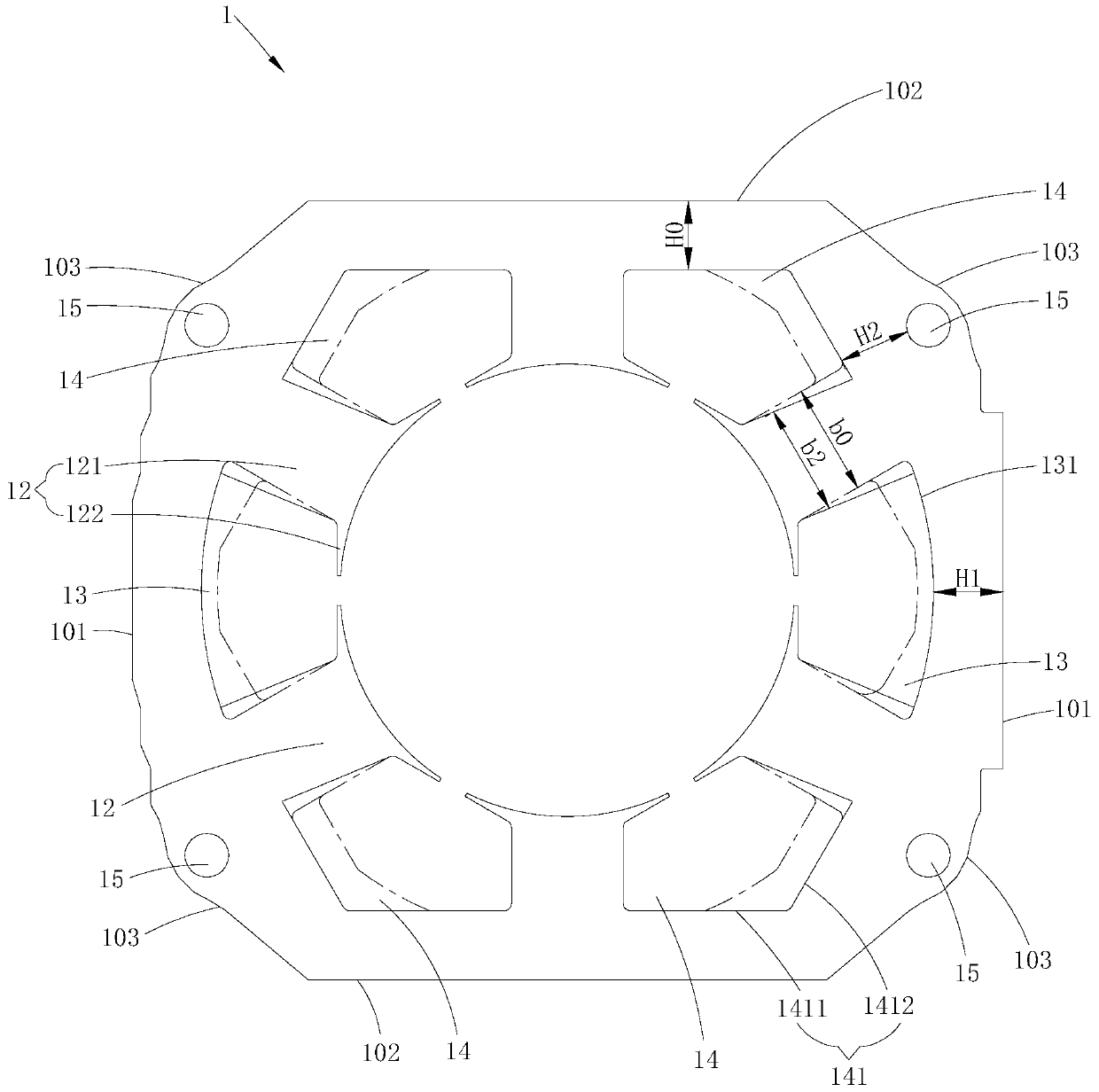
[0038] Such as figure 2 As shown, the same as the first embodiment, the method for increasing the area of ​​the stator core slots provided by this embodiment is also to increase the recessed depth of the stator slots recessed toward the outer edge 101 of the first straight side to form The first stator slot 13 and the bottom slot walls of the stator slots that are recessed towards the corner outer edge 103 and the second straight outer edge 102 at the same time face in a way that the distance H0 between the second straight outer edge 102 remains unchanged. The corner outer edge 103 is concavely extended to form the second stator slot 14, and also the distance H1 from the bottom slot wall 131 of the first stator slot 13 to the first straight outer edge 101, the bottom slot wall of the second stator slot 14 The distance H2 from 141 to the positioning hole 15 is set to be greater than or equal to the distance H0 from the bottom wall 141 of the second stator slot 14 to the second...


PUM


Abstract

The invention is suitable for the field of electric motors and discloses a method for increasing the slot area of ​​a stator core, a stator core, a stator and a motor. The method for increasing the slot area of ​​a stator core is specifically: moving the outer edges of the stator core toward the first straight edge. The recessed depth of the recessed stator slot is increased to form a first stator slot, and the bottom groove walls of the stator slots that are recessed toward the corner outer edge and the second straight side outer edge are positioned relative to the second straight side. The distance between the outer edges remains unchanged and is concavely extended toward the outer edge of the corner to form a second stator slot, and the distance from the bottom slot wall of the first stator slot to the first straight outer edge is set to be greater than or equal to the second stator The distance from the groove bottom groove wall to the outer edge of the second straight edge simultaneously translates or extends the tooth neck of the stator teeth located between the adjacent first stator groove and the second stator groove toward the side where the first stator groove is located. On the premise of ensuring that the minimum yoke thickness of the stator core remains unchanged, it increases the slot area of ​​the stator core and reduces the cost of the motor.

Description

technical field [0001] The invention belongs to the field of motors, in particular to a method for increasing the slot area of ​​a stator core, a stator core, a stator and a motor. Background technique [0002] Such as image 3 As shown, in an existing motor, the outline of the stator core is roughly rectangular, and the shape and size of the stator slots are the same, but the thickness of the yoke corresponding to each stator slot is not the same, wherein , and at the same time, the thickness H0' of the yoke at the recessed stator slot facing the corner outer edge 103' and the second straight edge outer edge 102' is the smallest. The structural shape of the stator core is unreasonable, which leads to the following disadvantages in the specific application of the motor: 1) The effective slot area of ​​the stator slot is small, so that the number of winding turns of the stator winding is small, and in order to ensure Due to the high efficiency of the motor, the stator windin...

Claims


Application Information

Patent Timeline
Patent Type & Authority Patents(China)
IPC IPC(8): H02K1/16
Inventor 彭光明赵丽丹王飞陈金涛
Owner GUANGDONG WELLING ELECTRIC MACHINE MFG
Learn More