Gear mechanism, movement and clock
A technology of gear trains and movements, which is applied to gear mechanisms, clocks, mechanically driven clocks, etc. It can solve the problems of non-insertion, reduced assembly, and inability to visually see the position of the transmission gear or the position of the pointer gear in the shaft support hole. , to achieve the effects of suppressing wobbling, shortening the shaft length, and suppressing the deviation of the needle movement
- Summary
- Abstract
- Description
- Claims
- Application Information
AI Technical Summary
Problems solved by technology
Method used
Image


Examples
no. 1 Embodiment approach
[0052] [clock]
[0053] A mechanical body including a driving part of a timepiece is generally referred to as a "movement". The finished state in which a dial and hands are attached to the movement and incorporated into a watch case is called the "complete" of the watch.
[0054] Of the two sides of the bottom plate constituting the watch base plate, the side with the glass of the watch case, that is, the side with the dial is referred to as the "back side" of the movement. In addition, the side opposite to the dial that has the case back cover of the timepiece case among both sides of the bottom plate is referred to as the "front side" of the movement.
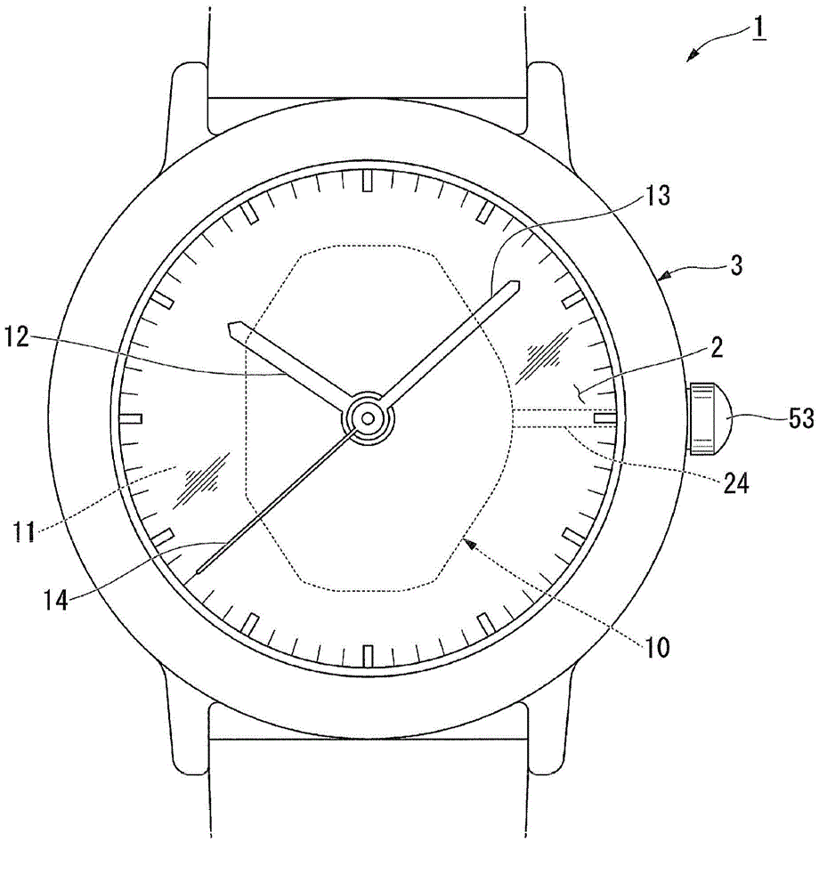
[0055] figure 1 It is an external view showing the timepiece 1 according to the embodiment of the present invention.
[0056] Such as figure 1 As shown, the complete watch 1 has a movement 100 , a dial 11 and hands 12 - 14 inside a watch case 3 composed of a case back cover (not shown) and a glass 2 .
[0057] The dial 1...
no. 2 Embodiment approach
[0118] Next, a second embodiment of the present invention will be described. Figure 8 It is a partial sectional view showing the movement 110 according to the second embodiment of the present invention. The difference between the movement deviation suppressing mechanism 131 of this embodiment and the above-mentioned first embodiment is that a pressing force applying portion 190 is formed on the back object presser (back object presser) 130 . In addition, in the following description, the detailed description will be omitted for the same structural parts as those of the first embodiment, and only the different parts will be described.
[0119] Such as Figure 8 As shown, in the movement 110 of the present embodiment, the movement deviation suppression mechanism 131 has a pressing member 170 , a support portion 180 , and a pressing force applying portion 190 .
[0120] The support portion 180 has: a support seat 181 formed on the upper surface of the bottom plate 20 ; and a g...
no. 3 Embodiment approach
[0135] Next, a third embodiment of the present invention will be described. In the hand movement deviation suppressing mechanism 231 of the present embodiment, the difference from the above-mentioned embodiment is that the pressing force applying portion 290 is formed on the base plate 20 . In addition, in the following description, the detailed description will be omitted for the same structural parts as those of the first and second embodiments, and only the different parts will be described. Figure 10 It is a sectional view showing the movement 210 of the third embodiment. Figure 11 It is a perspective view looking at the movement 210 from the front side.
[0136] Such as Figure 10 , Figure 11 As shown, in the movement 210 of this embodiment, the support portion 280 of the movement deviation suppression mechanism 231 has: a support base 81 , a guide pin 282 erected from the support base 81 , and a guide pin formed on the outer peripheral side of the support base 81 ....
PUM
 Abstract
Description
Claims
Application Information
 - Generate Ideas
- Intellectual Property
- Life Sciences
- Materials
- Tech Scout
- Unparalleled Data Quality
- Higher Quality Content
- 60% Fewer Hallucinations
Browse by: Latest US Patents, China's latest patents, Technical Efficacy Thesaurus, Application Domain, Technology Topic, Popular Technical Reports.
© 2025 PatSnap. All rights reserved.Legal|Privacy policy|Modern Slavery Act Transparency Statement|Sitemap|About US| Contact US: help@patsnap.com