Optical coupling module

A technology of optical coupling and rod body, which is applied in the field of optical coupling modules, can solve the problems of increasing the volume of connecting parts, such as complex volume, impact resistance, drop difference, and inability to talk about it, so as to achieve good anti-deformation effect, improve mechanical strength, and ensure the fixing effect. Effect

Active Publication Date: 2015-09-16
安徽中科瀚海光电技术发展有限公司
View PDF6 Cites 0 Cited by
  • Summary
  • Abstract
  • Description
  • Claims
  • Application Information

AI Technical Summary

Problems solved by technology

[0006] For this reason, it was proposed: first align and couple the two collimators on a high-precision optical detection platform, and then stick the above two collimators on a strip-shaped connector made of plastic or glass, Realize the fixation and calibration of the collimator; however, there is one-sided contact between the long strip connector and the collimator, the fixing effect is poor and the long strip connector itself is also deformed, so the actual solution effect is not good ideal;
[0007] Later, it was proposed to change the strip-shaped connector into an L-shaped connector. On the one hand, the deformation resistance of the L-shaped connector is enhanced, and the L-shaped connector is connected to the collimator from two sides, which helps However, after actual testing, this scheme is still not suitable for use in factories and mines. There are problems such as impact resistance, drop difference, and easy deformation in high-dust and humid environments. Scholars have proposed further improvement schemes: such as the cross-section The L-shaped positioning plate is fixed on a block to strengthen the fixing effect; or directly select a large block material, directly slot on the block and fix the collimator; or connect multiple pairs of collimators in parallel, By taking the average value to overcome the problem of poor coupling between collimators and decreased precision caused by deformation
The above-mentioned solutions, when improving or maintaining the coupling degree of the collimator, are all achieved by increasing the volume of the connecting piece or in a complicated way
The increase in the volume of the connecting piece requires a corresponding increase in the volume of the reprinted connecting piece and the detection front end of the collimator, making the product bloated and not suitable for placement at the point to be tested; in addition, because the outstanding feature of TDLAS technology is the detection terminal (Front end) does not need a power supply, only optical signals are used to achieve sampling, and electrical equipment is placed at the remote end; that is, the detection terminal (front end) is not equipped with an electric ventilation device, and the more complex the structure of the connector and its accessories , The larger the volume, the more it affects the exchange rate and effect between the detection terminal (front end) and the ambient gas to be detected. The ambient air flow cannot enter the detection terminal (front end) in time, and the detection accuracy is out of the question.

Method used


Image

  • Optical coupling module
  • Optical coupling module
  • Optical coupling module

Examples


Embodiment 1

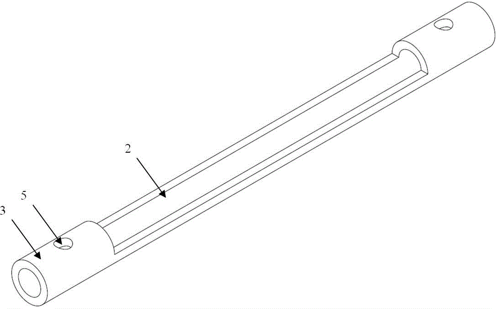
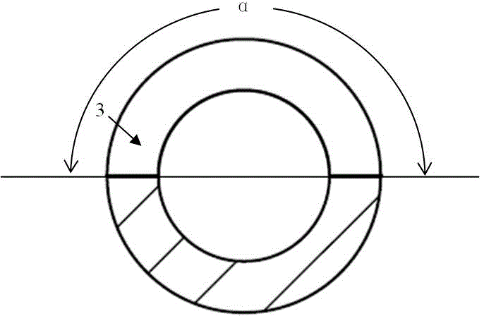
[0041] see figure 1 , the optical coupling module, whose shaft is in the shape of a cylindrical tube; there is a notch 2 on the top of the optical coupling module along the long axis, see figure 2 ; The length L2 of the notch 2 is between 10-1600mm; the angle α between the two long sides of the notch 2 is between 160° and 210°, see image 3 The two ends of the optical coupling module are the coupling fixing cylinder 3 for fixing the collimator 1, and the coupling fixing cylinder 3 is provided with a through positioning hole 5. The preferred solution is to open a pair of positioning holes 5 in the vertical direction and horizontal direction of the coupling and fixing cylinder 3, and match with adjusting nuts to fine-tune and position the collimator 1 .

Embodiment 2

[0043] see Figure 4 , the optical coupling module, whose shaft is in the shape of a cylindrical tube; there is a notch 2 on the top of the optical coupling module along the long axis, see figure 2 ; The length L2 of the notch 2 is between 10-80mm; the angle α between the two long sides of the notch 2 is between 190° and 210°, see image 3 The two ends of the optical coupling module are the coupling fixing cylinder 3 for fixing the collimator, and the coupling fixing cylinder 3 is provided with through positioning holes 5 . see Figure 5 , Mesh cylinders 6 are provided in the coupling and fixing cylinders 3 . see Figure 6 , insert the collimator 1 covered with the mesh tube 6 on the tube wall into the coupling and fixing tube 3 respectively, after adjusting and coupling the collimator 1 on both sides, and then drip 5 glue from the positioning hole, the glue is in the alignment Under the action of the siphon between the collimator 1, the mesh cylinder 6 and the coupling a...

Embodiment 3

[0046] see Figure 7 , the optical coupling module, whose shaft is in the shape of a cylindrical tube; there is a notch 2 on the top of the optical coupling module along the long axis, see figure 2 ; The length L2 of the notch 2 is between 10-1600mm; the angle α between the two long sides of the notch 2 is between 160° and 210°, see Figure 9 The two ends of the optical coupling module are the coupling fixing cylinder 3 for fixing the collimator, and the coupling fixing cylinder 3 is provided with through positioning holes 5 . see Figure 8 , there is a shallow groove 7 along the long axis direction at the bottom of the rod body of the optical coupling module. Figure 9 .


PUM

PropertyMeasurementUnit
The inside diameter ofaaaaaaaaaa
Wall thicknessaaaaaaaaaa
Lengthaaaaaaaaaa

Abstract

The invention relates to a photosensitive terminal, in particular, an optical coupling module. As for harsh use environment of TDLAS technology, a photosensitive terminal which is applicable to places such as mines and underground which require dust prevention, damp prevention and ventilation does not exist, while, the invention provides such a photosensitive terminal. The photosensitive terminal is in the shape of a cylindrical tube; a notch along the long axis of the optical coupling module is formed at the top of the optical coupling module; the length of the notch ranges from 10 to 1600mm; the included angle alpha between two long edges of the notch ranges from 160 degrees to 210 degrees; two ends of the optical coupling module are coupling fixing cylinders for fixing a collimator; and a perforating positioning hole is formed in the coupling fixing cylinders respectively. The optical coupling module of the invention has the advantages of small size, high anti-temperature deformation ability and high gas guide ability. With the optical coupling module of the invention adopted, a gas sampling end of equipment using the TDLAS technology can work under complex environments such as mines and underground.

Description

technical field [0001] The invention belongs to the field of gas monitoring equipment, and in particular relates to an optical coupling module. Background technique [0002] At present, with the rapid development of economic construction, the use of hazardous chemical gases is becoming more and more extensive. The biggest challenge faced by its production, storage, transportation and other links is safety issues, which threaten people's health and safety at all times and cause social stability. adverse effects. One of the important reasons for the frequent occurrence of dangerous chemical gas accidents and serious consequences in my country is the backwardness of its detection and monitoring technology. [0003] At present, the products used for monitoring hazardous chemical gases on the market are generally traditional electrochemical sensors. Its working principle is to convert the concentration value of the gas to be measured into a voltage signal through the catalytic ...

Claims


Application Information

Patent Timeline
IPC IPC(8): G02B6/42
Inventor 白薇
Owner 安徽中科瀚海光电技术发展有限公司
Why Eureka
Try Eureka