Eureka AIR delivers breakthrough ideas for toughest innovation challenges, trusted by R&D personnel around the world.

Printed circuit board automatic optical detection method

An automatic optical inspection, printed circuit board technology, applied in the direction of material analysis, measuring device, scientific instrument, etc. by optical means, can solve the problems of difficult to achieve movement trajectory, misjudgment of printed circuit board, missed defect detection, etc. Automatic optical inspection efficiency, reducing the effect of misjudgment or missed defect detection

Active Publication Date: 2015-09-16
DONGGUAN WERY DOOD CIRCUIT BOARD EQUIP
View PDF6 Cites 8 Cited by
  • Summary
  • Abstract
  • Description
  • Claims
  • Application Information

AI Technical Summary

Problems solved by technology

[0003] However, the printed circuit board under test transported by the rollers may be in a bumpy state due to the jumping of the rollers during the traveling process, so it is difficult to achieve a fixed motion track at the micro level
Due to the above problems, traditional automatic optical inspection methods for printed circuit boards may have misjudgments or missed defects in the inspection process of printed circuit boards.

Method used


Image

  • Printed circuit board automatic optical detection method
  • Printed circuit board automatic optical detection method

Examples


Embodiment Construction

[0020] The following will clearly and completely describe the technical solutions in the embodiments of the present invention. Obviously, the described embodiments are only some of the embodiments of the present invention, rather than all the embodiments. Based on the embodiments of the present invention, all other embodiments obtained by persons of ordinary skill in the art without making creative efforts belong to the protection scope of the present invention.

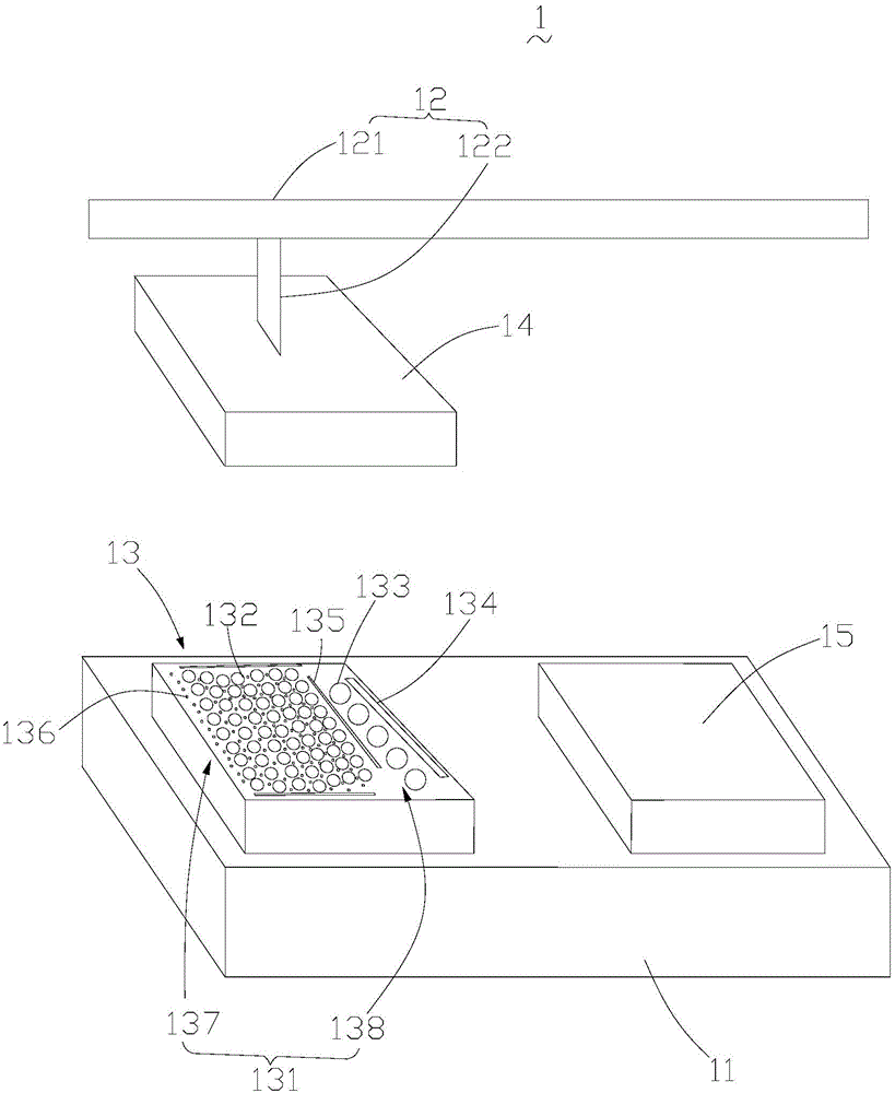
[0021] The printed circuit board automatic optical inspection method provided by the present invention can be applied in such as figure 1 A printed circuit board automated optical inspection system 100 is shown. The printed circuit board automatic optical inspection system 100 includes a base 11 , a displacement electric cylinder 12 , a first object stage 13 , a second object stage 14 and a sorting platform 15 . Preferably, in a specific embodiment, the printed circuit board automatic optical inspection system 100 m...


PUM


Abstract

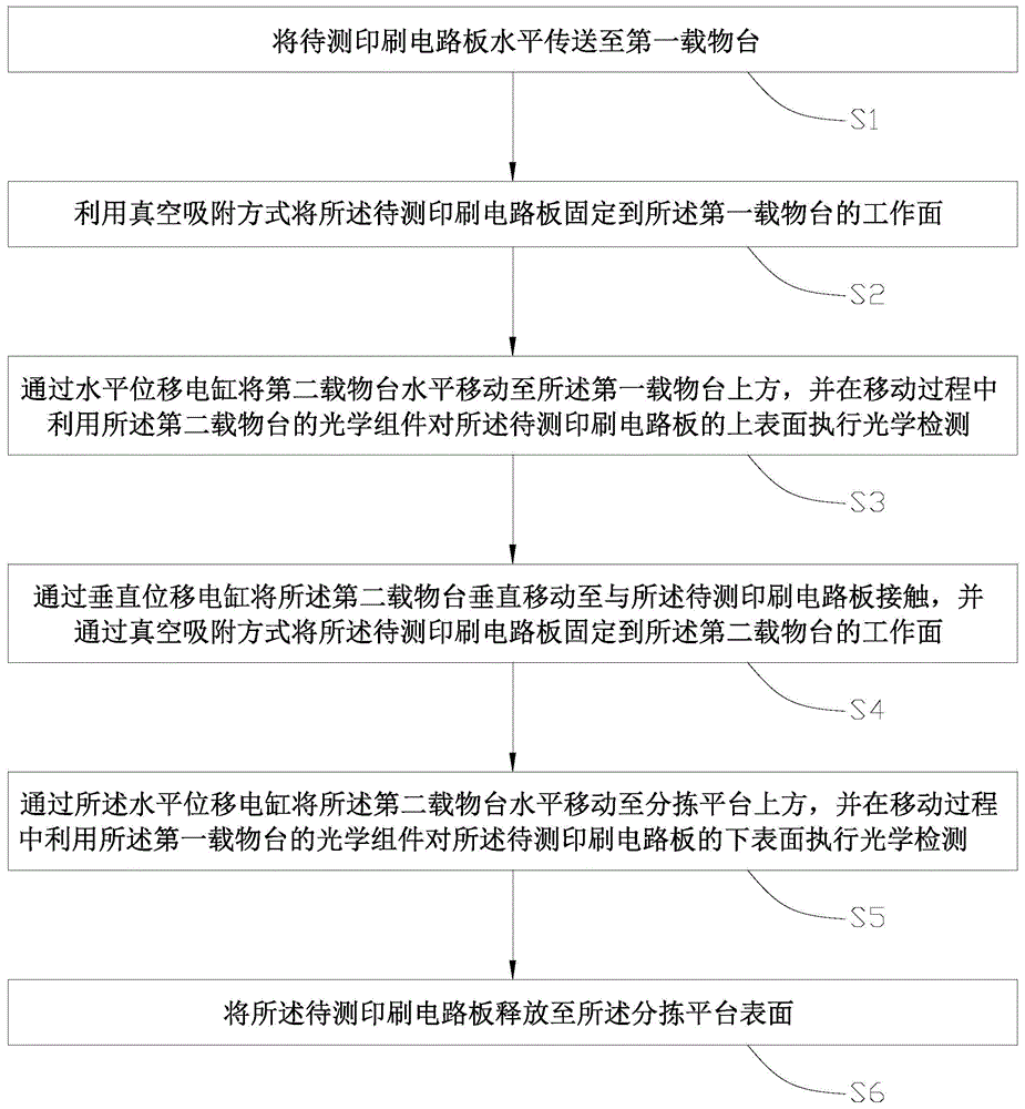
The invention provides a printed circuit board automatic optical detection method. The printed circuit board automatic optical detection method comprises 1, fixing a printed circuit board to be detected onto a working face of a first objective table by a vacuum adsorption method, 2, horizontally moving a second objective table to a position above the first objective table by a horizontal displacement electric cylinder, and simultaneously, carrying out optical detection on the upper surface of the printed circuit board to be detected by an optical module on the second objective table in movement, 3, vertically moving the second objective table by a vertical displacement electric cylinder so that the second objective table contacts with the printed circuit board to be detected, and fixing the printed circuit board to be detected to a working face of the second objective table by a vacuum adsorption method, and 4, horizontally moving the second objective table by the horizontal displacement electric cylinder and simultaneously, carrying out optical detection on the lower surface of the printed circuit board to be detected by an optical module on the first objective table in movement.

Description

technical field [0001] The present invention relates to the field of printed circuit board (Printed Circuit Board, PCB) manufacturing, in particular, to an automatic optical inspection (Automated Optical Inspection, AOI) method for printed circuit boards. Background technique [0002] At present, in the manufacturing process of printed circuit boards, automatic optical inspection solutions are mainly used to detect circuit defects on both sides of printed circuit boards, such as circuit shorts, open circuits, pinholes, scratches, thin lines, thick lines, and dog teeth. The traditional automatic optical inspection method for printed circuit boards is to set the upper and lower line-scan cameras on the top and bottom of the line-scan camera respectively, and the printed circuit board to be tested travels between the upper line-scan camera and the lower line-scan camera through the line In the process, the upper line array camera and the lower line array camera are used to take...

Claims


Application Information

Patent Timeline
Patent Type & Authority Applications(China)
IPC IPC(8): G01N21/956
Inventor 杨毅
Owner DONGGUAN WERY DOOD CIRCUIT BOARD EQUIP
Why Eureka
Eureka Blog
Learn More