Magneto-optical detection device

A detection device, magneto-optical technology, applied in the direction of optical testing flaws/defects, polarization influence characteristics, etc.

Active Publication Date: 2017-07-14
北京锦润汇泽科技发展有限公司
View PDF5 Cites 0 Cited by
  • Summary
  • Abstract
  • Description
  • Claims
  • Application Information

AI Technical Summary

Problems solved by technology

[0004] In order to solve the technical problems existing in the prior art, the object of the present invention is to provide a magneto-optical detection device with simple operation, short time consumption, high sensitivity and the ability to detect subtle defects

Method used


Image

  • Magneto-optical detection device

Examples


Embodiment Construction

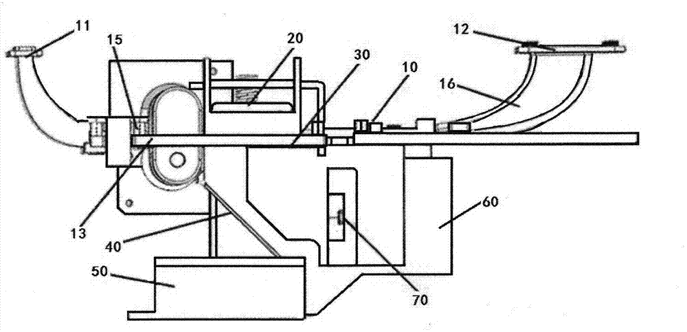
[0019] Such as figure 1 As shown, the present invention relates to a magneto-optical detection device, which includes a magnetic stripe moving mechanism 10, and the magnetic stripe moving mechanism 10 includes a magnetic stripe inlet 11 and a magnetic stripe outlet 12, and the magnetic stripe inlet 11 and the magnetic stripe outlet There is a magnetic strip moving path 13 between 12; on the moving path, a pressing plate 20 is arranged, and a magneto-optical film 30 is arranged below the moving path 13 and facing the position of the pressing plate 20, and the magneto-optic film 30 A spectroscopic sheet 40 , a polarized light source 50 and a camera 60 are arranged below. The polarized light source 50 is composed of a plane light source and a linear polarizer. The magneto-optical detection device also includes a single-chip microcomputer for controlling the polarized light source 50 , the magnetic strip moving mechanism 10 and the camera 60 . In the present invention, the camer...


PUM


Abstract

The invention relates to a magneto-optical detection device, which belongs to the technical field of metal material defect detection. The magneto-optical detection device of the present invention comprises a magnetic strip moving mechanism, the magnetic strip moving mechanism comprises a magnetic strip entrance and a magnetic strip exit, and a magnetic strip moving path is provided between the magnetic strip entrance and the magnetic strip exit; on the moving path, the method is provided with A pressure plate, a magneto-optical film is arranged below the moving path and facing the position of the pressure plate, and a spectroscopic sheet, a polarized light source, and a camera are arranged under the magneto-optic film; the pressure plate is used for pressing the magnetic strip on the On the magneto-optic film, the polarized light source is used to provide polarized light, and the polarized light is irradiated on the magneto-optic film after passing through the beam splitter, and the light reflected by the magneto-optic film is imaged by the camera after being refracted by the beam splitter. The magneto-optical detection device of the present invention judges and determines defects on the ferromagnetic metal surface by scanning the magnetic field information of the metal surface, and can realize non-destructive detection because the magnetic field is not affected by dust and paint.

Description

technical field [0001] The invention relates to the technical field of metal material defect detection, and more specifically, the invention relates to a magneto-optical detection device. Background technique [0002] Due to various reasons, there will be defects such as depressions and voids on the surface and inside of ferromagnetic metals. Metal surfaces cannot be directly observed if they are covered with paint, putty, coating, dirt, etc. For this purpose, ultrasonic testing, X-ray testing, magnetic particle testing and chemical imaging are commonly used in the prior art. For ultrasound imaging, the main drawback is that the resolution is not high, and it cannot form an intuitive image. X-ray detection: The equipment is too large to be harmful to people. Especially very inconvenient for mobile work, because the protection at this moment is difficult to do well. The resolution of magnetic particle flaw detection is too low, it can only detect larger defects, and it po...

Claims


Application Information

Patent Timeline
Patent Type & Authority Patents(China)
IPC IPC(8): G01N21/21G01N21/95
Inventor 殷涛刘东平牛建锋王锴
Owner 北京锦润汇泽科技发展有限公司
Why Eureka
Try Eureka