Oil conveying device of vehicle automatic transmission

A technology for automatic transmission and oil delivery, which is applied to transmission parts, transmission components, components with teeth, etc., can solve the problems of energy waste and increase the cost of automobile use, and achieve improved power transmission efficiency, fuel efficiency, and compact effect

Inactive Publication Date: 2015-09-16
FUXIN DARE AUTOMOTIVE PARTS
View PDF13 Cites 0 Cited by
  • Summary
  • Abstract
  • Description
  • Claims
  • Application Information

AI Technical Summary

Problems solved by technology

The oil delivery device of the general automatic transmission is driven by the output shaft of the engine to deliver the oil device. The speed of the oil delivery device of the automatic transmission with this structure increases with the increase of the engine speed. Under certain working conditions, the engine Working at high speed, the flow output of the oil delivery device of the automatic transmission is very large, but the systems of the automatic transmission do not need so much oil, which causes a lot of waste of energy and increases the use cost of the car

Method used


Image

  • Oil conveying device of vehicle automatic transmission
  • Oil conveying device of vehicle automatic transmission
  • Oil conveying device of vehicle automatic transmission

Examples


Embodiment Construction

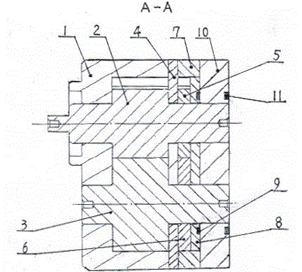
[0011] Examples, see attached Figure 1~3 The housing one 1, the partition plate 4, the housing two 7 and the upper end cover 10 of the vehicle automatic transmission oil delivery device are positioned through two relative positioning sleeves 12, and the two bolts 13 respectively pass through the positioning The central hole of the sleeve 12 is threadedly connected with the shell one 1 , and the shell one 1 , the partition plate 4 , the shell two 7 , and the upper end cover 10 are axially tightly connected. The partition plate 4 is provided with a partition plate oil discharge passage 4-1, the casing two 7 is provided with a casing two oil discharge passage 7-1, and the upper end cover 10 is respectively provided with an end cover oil discharge port one 10-1 It communicates with the oil discharge port 2 10-2 of the end cover, the oil discharge channel 4-1 of the partition plate, and the oil discharge channel 7-1 of the housing 2 in correspondence with each other. Drive gear o...


PUM


Abstract

The invention belongs to automobile parts and particularly relates to an oil conveying device of a vehicle automatic transmission. Positioning between a first shell (1), a separating plate (4), a second shell (7) and an upper end cover (10) is achieved through two opposite positioning sleeves (12), two bolts (13) penetrate through center holes of the positioning sleeves (12) to be connected with the first shell (1) in a threaded mode, the fastening connection among the first shell (1), the separating plate (4), the second shell (7) and the upper end cover (10) in the axial direction is achieved through the two bolts (13), a first driving gear (2) and a first driven gear (3) are installed in the inner cavity of the first shell (1), the other axial side of the first driving gear (2) penetrates through the separating plate (4) to be in interference connection with a second driving gear (5) in a penetrating mode, and the other axial side of the first driven gear (3) penetrates through the separating plate (4) to be in interference connection with a second driven gear (6) in a penetrating mode. The oil conveying device of the vehicle automatic transmission is provided with two oil absorbing cavities and two oil discharging cavities, the oil discharging cavities are independent respectively, and the oil conveying device of the vehicle automatic transmission has the advantages of being compact in structure and high in efficiency.

Description

technical field [0001] The invention belongs to auto parts, in particular to an oil conveying device for a vehicle automatic transmission. Background technique [0002] With the improvement of people's requirements for the driving comfort of automobiles, the popularity of automatic transmissions in cars at home and abroad has also increased, and more and more attention has been paid to the miniaturization of automatic transmissions and the reduction of energy consumption. The oil delivery device of the general automatic transmission is driven by the output shaft of the engine. The speed of the oil delivery device of the automatic transmission with this structure increases with the increase of the engine speed. Working at high speed, the flow output of the oil delivery device of the automatic transmission is very large, but the systems of the automatic transmission do not need so much oil, which causes a lot of waste of energy and increases the use cost of the car. Contents...

Claims


Application Information

Patent Timeline
IPC IPC(8): F16H57/04
CPCF16H57/04F16H57/0435F16H57/0436F16H2700/00
Inventor 王忠伟韩颖马东明何塞李文亮王龙滕越江涛何志刚冯文王兴马志俊张蕾
Owner FUXIN DARE AUTOMOTIVE PARTS
Why Eureka
Try Eureka