Corridor elevator control method

A control method and technology for elevators in corridors, applied to elevators, lifts, transportation and packaging in buildings, etc., can solve problems such as lack of coping strategies, interference of moving parts, equipment failures, etc., to prevent personnel injury and equipment damage, simplifying Line installation structure, the effect of improving stability

Active Publication Date: 2015-09-16
浙江道可道楼道电梯有限公司
View PDF6 Cites 8 Cited by
  • Summary
  • Abstract
  • Description
  • Claims
  • Application Information

AI Technical Summary

Problems solved by technology

[0005] 1) The control method of the corridor elevator is relatively simple. When encountering a fault, there is a lack of necessary coping strategies. For example, when the rail car is ascending or descending, when an obstacle is encountered, the existing corridor elevator cannot make reasonable emergency actions. It is easy to cause personal injury and equipment damage;
[0006] 2) The walking mode of the traction steel wire of the traction mechanism is unreasonable, which leads to the deviation and detachment of the traction steel wire, and the equipment failure is prone to occur;
[0007] 3) The upper sensing mechanism and the lower sensing mechanism on the pedal are usually connected to the control system with a wire harness, and the frequent retraction and release of the pedal is likely to cause damage to the wire harness, thus destroying the emergency protection performance;
[0008] 4) There is no corresponding detachment prevention structure for the steel wire rope used to realize pedal rotation and rail car drive, and the steel wire rope is easy to detach from the corresponding driving wheel or roller, which is easy to cause interference to moving parts and cause safety accidents;
[0009] 5) The setting of the compression spring of the safety emergency stop device is unreasonable. Most of the two compression springs are installed in an inner and an outer casing. Due to the limitation of the installation method, it is difficult to choose a matching model for the compression spring

Method used


Image

  • Corridor elevator control method
  • Corridor elevator control method
  • Corridor elevator control method

Examples


Embodiment Construction

[0037] The present invention will be further described in detail below in conjunction with the accompanying drawings and examples. The following examples are explanations of the present invention and the present invention is not limited to the following examples.

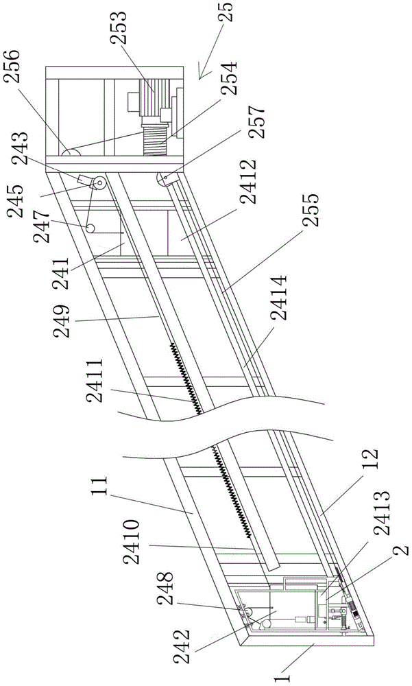
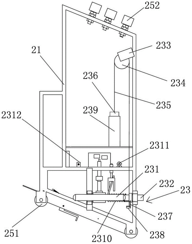
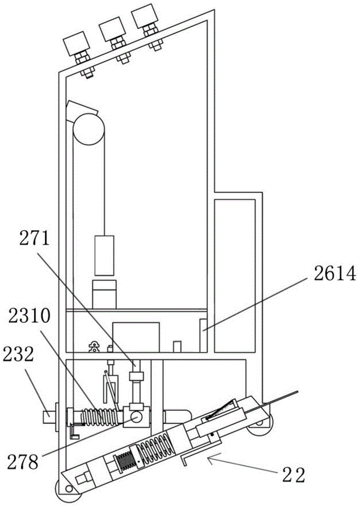
[0038] see Figure 1-Figure 11 , the corridor elevator of this embodiment includes an elevator bracket 1 for being installed on the stairs, a rail car device 2 for reciprocating up and down on the elevator bracket 1 and a control system for controlling the operation of the corridor elevator, the elevator bracket 1 is provided with an upper rail 11 and a lower rail 12 for the rail car device 2 to slide, and the upper rail 11 and the lower rail 12 are parallel to each other. The rail car device 2 includes a rail frame 21, a safety emergency stop device 22, a pedal mechanism 23 and a traction Mechanism 25, the upper end of track vehicle frame 21 is provided with the upper pulley 251 that is used to be slidably installe...


PUM


Abstract

The invention discloses a corridor elevator control method. When an elevator meets a barrier during descending, vertical reciprocating motion is performed, whether the barrier below the elevator exists or not is probed by triggering a limiting switch, a track frame can automatically descend to the bottom position on the condition that the barrier disappears, and the track frame is stopped on the condition that the barrier exists for a long time; the barrier is removed through personnel intervention, and the phenomena that the personnel are injured and equipment is damaged due to forcible descending are avoided; when the elevator meets a barrier during ascending, emergency braking is performed, the control right of a traction control button is cut off, a rider is prevented from conducting the ascending operation forcibly, and the phenomena that the personnel are injured and the equipment is damaged due to forcible ascending are avoided.

Description

technical field [0001] The invention relates to a control method of special equipment, in particular to a control method of a corridor elevator. Background technique [0002] In the multi-storey residences (5-9 floors) built in my country in the 1980s and 1990s, the vertical traffic problem of multi-storey residences has become the most critical problem for the elderly population in cities due to the absence of elevators. People often sit on the building supervisor. Governments at all levels are also trying to find a way to solve this problem, especially Guangzhou, Shanghai, Beijing and other places are piloting the scheme of installing box elevators in old multi-storey houses, but during the pilot process, it is found that the old multi-storey Adding box-body elevators to residential buildings has complex approval procedures, unapproved land area occupied by the shaft, high renovation costs, long construction period, and differences in opinions arising from unequal benefits...

Claims


Application Information

Patent Timeline
Patent Type & Authority Applications(China)
IPC IPC(8): B66B5/02B66B5/26B66B13/02
CPCB66B5/02B66B5/26B66B9/0807B66B13/02
Inventor 竺圣刚
Owner 浙江道可道楼道电梯有限公司
Why Eureka
Try Eureka