Counter-steering device for propulsion and directional control in water
A technology of steering device and direction control, which is applied in the direction of steering and steering with propulsion components, which can solve the problems of heavy weight, complex structure and high cost, and achieve the effect of reducing installation
- Summary
- Abstract
- Description
- Claims
- Application Information
AI Technical Summary
Problems solved by technology
Method used
Image


Examples
Embodiment 1
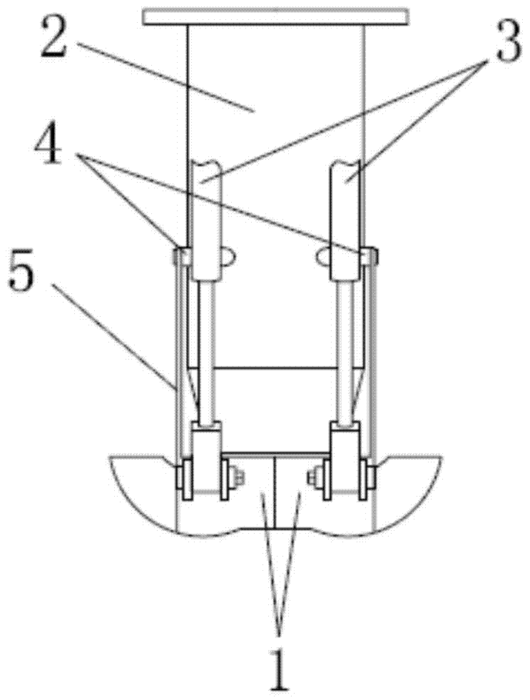
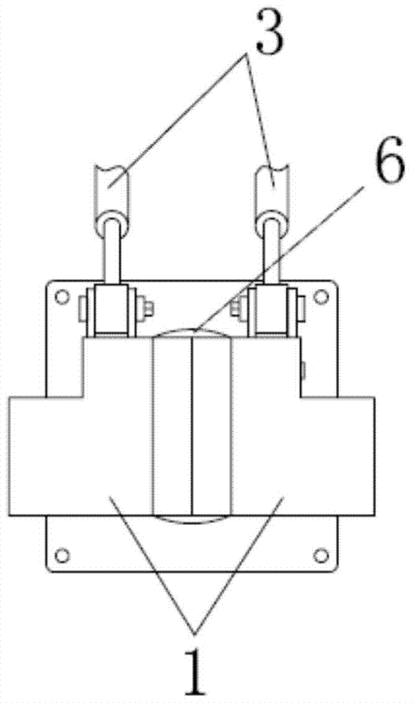
[0049] like figure 1 As shown, this embodiment discloses a reverse steering device for underwater propulsion and direction control, which includes a rudder 1 , a water jet 2 and a displacement device 3 .
[0050] Wherein, the number of the water jet propeller 2 is one. The rudders are arranged as a pair, and are relatively distributed on both sides of the vertical central axis of the water spout 6 . At the same time, each rudder 1 is connected to a shifting device 4, which is represented by a telescopic mechanism in this embodiment, and adopts hydraulic pressure, push-pull shaft or electric mode for telescopic operation, and is intended to drive the rudder 1 to deviate or Returns to the outside of the spout, but other mechanisms that serve the same purpose could be substituted.
[0051] Among them, the rudder is relatively distributed on the vertical central axis of the water nozzle, the purpose is to make the displacement device connected with it and give the push-pull forc...
Embodiment 2
[0060] The difference between this embodiment and Embodiment 1 is that the rudder 1 is arranged laterally on both sides of the vertical central axis of the water jet 6 of the water jet propeller 2 through the connecting strut 5 . Since the rudder 1 is arranged laterally, the hinge point 4 is located at the middle and lower part of the outer wall of the water jet propeller 2 .
[0061] The reason why the hinge point 4 is arranged on the middle and lower part of the outer wall of the water jet propeller 2 is that the rudder 1 is arranged on the longitudinal plane of the water jet 6 in a horizontal manner, because the rudder 1 is positioned on the side of the displacement device 3. During the push-pull process, since its own length is relatively small in the horizontal dimension relative to the longitudinal dimension, when it is necessary to change the force exerted by the sprayed water from the water nozzle 6 on the reverse rudder 1, the reverse rudder 1 is vertical to the water ...
Embodiment 3
[0067] The only difference between this embodiment and Embodiment 1 is that the rudder 1 on the left side is arranged laterally, so the corresponding hinge point 4 is arranged in the middle and lower part of the water jet propeller 2, as Figure 9 As shown, the reverse rudders 1 connected to the two water jets 2 are connected in different ways, and the principle of setting the hinge point 4 there is the same as that of Embodiment 2, and will not be repeated here. Of course, it is also possible that the rudder positioned on the left side is arranged longitudinally, and the rudder 1 positioned on the right side is arranged horizontally.
[0068] Depend on Figure 9It can be seen that it shows the state of turning counterclockwise in situ, the left rudder 1 does not deviate from the water nozzle 6, and the right rudder 1 completely deviates from the water nozzle 6, so the water flow on the left is moved forward by the rudder 1 The water flow on the right side is sprayed directly...
PUM
 Abstract
Description
Claims
Application Information
 - R&D
- Intellectual Property
- Life Sciences
- Materials
- Tech Scout
- Unparalleled Data Quality
- Higher Quality Content
- 60% Fewer Hallucinations
Browse by: Latest US Patents, China's latest patents, Technical Efficacy Thesaurus, Application Domain, Technology Topic, Popular Technical Reports.
© 2025 PatSnap. All rights reserved.Legal|Privacy policy|Modern Slavery Act Transparency Statement|Sitemap|About US| Contact US: help@patsnap.com