
A two-station rotary table

A rotary table, two-station technology, applied in the direction of manufacturing tools, metal processing equipment, metal processing mechanical parts, etc., can solve the problems of difficult control of working speed, oil leakage of hydraulic cylinders, and high hardware cost, and achieves simple structure and noise. Small, high-efficiency effect

Inactive Publication Date: 2017-07-18
HUBEI UNIV OF AUTOMOTIVE TECH
View PDF5 Cites 0 Cited by
  • Summary
  • Abstract
  • Description
  • Claims
  • Application Information

AI Technical Summary

Problems solved by technology

However, due to the hydraulic drive, it is difficult to achieve constant acceleration motion, the working speed is not easy to control, and it is prone to problems such as oil leakage from the hydraulic cylinder, impact during the transmission process, unstable work, and noise; during the drive process of the servo motor, constant acceleration motion can be achieved. The rotary speed of the worktable is easy to control, but the required drive torque is large, the hardware cost is high, and the cost is expensive

Method used


Image

  • A two-station rotary table
  • A two-station rotary table
  • A two-station rotary table

Examples


Embodiment Construction

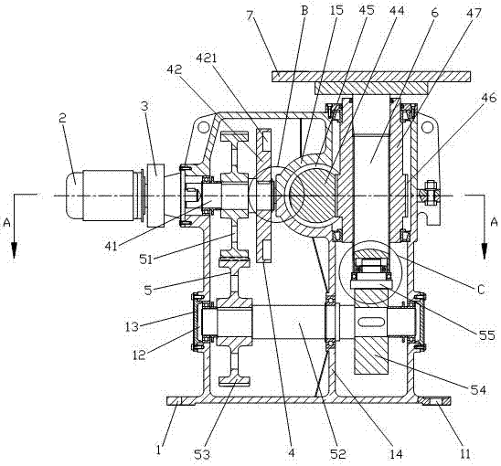
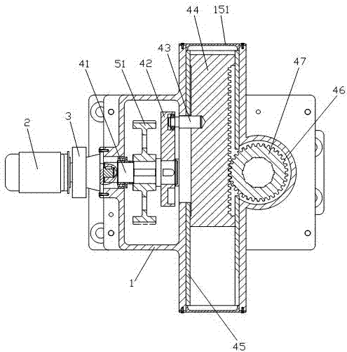
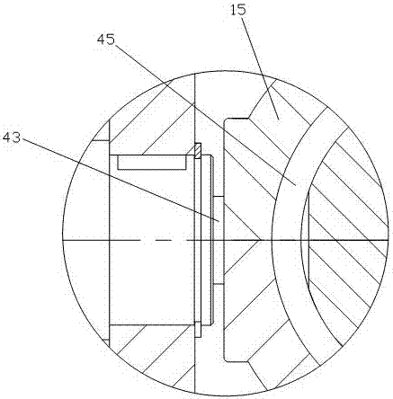
[0018] Such as Figures 1 to 4 As shown, the two-station rotary table of the present invention includes a cabinet 1, a motor 2, a reducer 3, an indexing mechanism 4, a lifting mechanism 5, a rotating shaft 6 and a table top 7.

[0019] The periphery of the bottom end of the case 1 is provided with a case installation hole 11, and the middle and lower end is symmetrically provided with transmission shaft installation holes 12 on the opposite side walls, and a transmission shaft protective end cover 13 is installed at the outer end of the transmission shaft installation hole 12; 1. The interior is divided into two left and right chambers by the support wall 14. The upper end of the support wall 14 is horizontally connected with a rack installation pipe 15; the rack installation pipe 15 is located in the left chamber of the chassis 1, and its two ends The nozzles are respectively closed by the end caps 151 of the rack installation tubes;

[0020] The motor 2 is mounted on the ou...


PUM


Abstract

The invention relates to a two-station rotating working table which comprises a machine box, a motor, a speed reducer and a table top. The working table further comprises a transfer mechanism installed in the machine box, a lifting mechanism and a rotating shaft. The transfer mechanism comprises a main transmission shaft, a transfer cam, a rack, a transfer gear and a gear shaft. One end of the main transmission shaft is connected with the power output end of the motor, the other end of the main transmission shaft is in assembling connection with the transfer cam, the transfer cam is connected with the rack, the transfer gear and the gear shaft are of an integrated structure, and the transfer gear is arranged on an outer wall of the gear shaft and is in matched meshing with the rack. The two ends of the gear shaft are in assembling connection with an inner cavity wall of the machine box. The lifting mechanism comprises a main transmission gear, an auxiliary transmission shaft, an auxiliary transmission gear, a lifting cam, a T-shaped shaft, a radial ball bearing and a thrust bearing. The two-station rotating working table is simple and rational in structural design, works stably, is high in working efficiency and low in cost, and can achieve uniform acceleration movement and accurately control lifting and transfer movement speeds.

Description

technical field [0001] The invention relates to a rotary worktable, in particular to a two-station rotary worktable driven by a common motor and realized by a cam mechanism for lifting and indexing. Background technique [0002] In many machine tool processing occasions, the parts to be processed are required to be exchanged between the loading station and the processing station. A two-station rotary table can do the job. At present, most of the rotary tables driven by hydraulic drive or servo motor are used in the market. The hydraulically driven rotary table is powered by a hydraulic cylinder, which drives the rack and pinion mechanism to drive the table to rotate, and the lifting movement of the table can be directly driven by the hydraulic cylinder. However, due to the hydraulic drive, it is difficult to achieve constant acceleration motion, the working speed is not easy to control, and it is prone to problems such as oil leakage from the hydraulic cylinder, impact dur...

Claims


Application Information

Patent Timeline
Patent Type & Authority Patents(China)
IPC IPC(8): B23Q1/26
CPCB23Q1/26
Inventor 邱新桥郑金叶
Owner HUBEI UNIV OF AUTOMOTIVE TECH
Learn More