
Earthquake-resistant cabinet

An anti-seismic cabinet, integrated technology, applied in the direction of anti-seismic equipment, rack/frame structure, substation/switchgear frame, etc., to achieve high precision, solve special requirements for seismic resistance, and easy processing.

Inactive Publication Date: 2015-09-09
KEHUA DATA CO LTD +1
View PDF7 Cites 5 Cited by
  • Summary
  • Abstract
  • Description
  • Claims
  • Application Information

AI Technical Summary

Problems solved by technology

[0006] In view of this, the purpose of the present invention is to provide an anti-seismic cabinet, which has the advantages of high precision, easy processing, and strong anti-seismic performance, and solves the special requirements for the anti-seismic performance of the cabinet in special applications such as nuclear power

Method used


Image

  • Earthquake-resistant cabinet
  • Earthquake-resistant cabinet
  • Earthquake-resistant cabinet

Examples


Embodiment 1

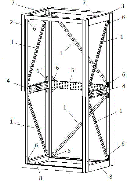
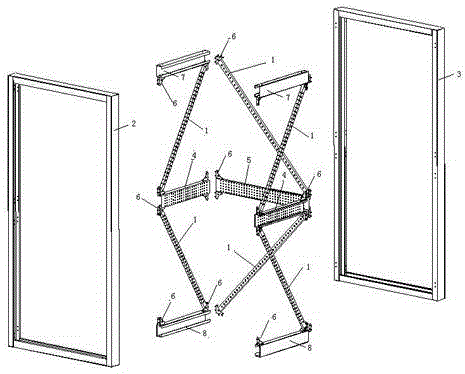
[0028] Such as figure 1 as well as figure 2 As shown, the present embodiment provides a kind of anti-seismic cabinet, which is a cuboid frame. The front and rear sides of the cuboid frame include a front frame 2 and a rear frame 3, and the middle part of the rear frame 3 is provided with a rear beam 5; The first side and the second side of the cuboid frame are respectively provided with an upper beam 7 and a lower beam 8, which are used to weld the front frame 2 and the rear frame 3 to form a cabinet body; the middle part of the first side and the second side The middle part is provided with side beams 4; the first side and the second side are divided into two rectangles by the side beams 4, and the rear frame is divided into two rectangles by the rear beams, each An angle iron 6 is provided at each of the four corners of the rectangle, and a reinforcement beam 1 is provided at each diagonal position of the rectangle to divide the rectangular structure into stable triangular...

Embodiment 2

[0040] Such as Figure 6 As shown, this embodiment provides an anti-seismic cabinet in the field of nuclear power, including a cuboid frame, each of the four corners of the rectangle of the cuboid frame is provided with an angle iron, and at least two of the side walls of the cuboid frame Reinforcing beams are arranged in the diagonal direction to divide the rectangular structure into stable triangular structures.

[0041] In this embodiment, the cuboid frame and the angle iron are connected and fixed by riveting, welding or a combination of riveting and welding, and the reinforcing beam and the angle iron are fixed by welding, screw and nut connection or welding and screw and nut Combined way to connect and fix.

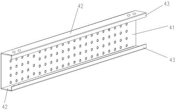
[0042] In this embodiment, the reinforcing beam is provided with several small holes to reduce weight.

[0043] In summary, compared with the prior art, the entire frame of the present invention is fixed by riveting and welding, and there are reinforcing beams on ...


PUM


Abstract

The present invention relates to an earthquake-resistant cabinet which is a rectangular frame. The front and back sides of the rectangular frame comprise a front frame and a back frame. The middle of the back frame is provided with a back cross beam. Upper and lower cross beams are arranged above and under the first side face and the second side face of the rectangular frame. The upper and lower cross beams and the front and back frames are integratedly welded to form a cabinet body. The middle of the first side face and the middle of the second side face are provided with side cross beams. The first side face and the second side face are cut by the side cross beams to be two rectangles. The back frame is cut by the back cross beam to be two rectangles. The four corners of each rectangle are provided with an angle iron. The diagonal position of each rectangle is provided with a reinforcing beam for dividing a rectangle structure into stable triangular structures. The earthquake-resistant cabinet has the advantages of high accuracy, easy processing and strong earthquake-resistant performance, and the special requirement for the earthquake-resistant performance of the cabinet by nuclear power and other special occasions is solved.

Description

technical field [0001] The invention relates to a cabinet body, in particular to an anti-seismic cabinet body. Background technique [0002] At present, in some nuclear power application fields that require extremely high reliability, they pay great attention to the earthquake resistance of the equipment. Because the existing cabinets do not consider the occurrence of such extremely low probability earthquakes, they often do not pay attention to this part in structural design. Or it can only meet the requirements of some conventional earthquakes, but it still cannot meet the requirements of rare large earthquakes. Some cabinets use a large number of welding and structural parts to ensure earthquake resistance, which has no advantages in precision, man-hours, and cost. [0003] The comparison documents most similar to the present invention include "GGD Type Assembled Low-Voltage Power Distribution Cabinet Skeleton" and "Earthquake-Resistant Auxiliary Frame of Electrical Cabi...

Claims


Application Information

Patent Timeline
Patent Type & Authority Applications(China)
IPC IPC(8): H02B1/01H05K7/18
CPCH02B1/013H02B1/014H02B1/54
Inventor 江立佳林艺成付明星苏先进李明成
Owner KEHUA DATA CO LTD
Learn More