
A downhole real-time sand mixer

A sand mixer and center hole technology, applied in wellbore/well components, production fluids, earthwork drilling, etc., can solve the problems of long sand concentration control process, inability to carry out real-time control, etc., to expand volume and increase pressure. The effect of fracturing stimulation and fracturing construction safety

Active Publication Date: 2017-07-07
PETROCHINA CO LTD
View PDF5 Cites 0 Cited by
  • Summary
  • Abstract
  • Description
  • Claims
  • Application Information

AI Technical Summary

Problems solved by technology

[0004] The purpose of the present invention is to overcome the problem that the existing sand concentration control process takes too long and cannot be controlled in real time

Method used


Image

  • A downhole real-time sand mixer
  • A downhole real-time sand mixer
  • A downhole real-time sand mixer

Examples


Embodiment 1

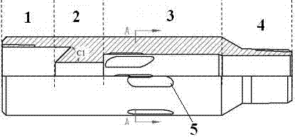
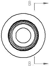
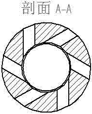
[0024] This embodiment provides a figure 1 , figure 2 , image 3 , Figure 4 The downhole real-time sand mixer shown is a cylinder, and the center hole of the cylinder is the center hole 1 of the first section, the center hole 2 of the second section, and the center hole 3 of the third section from top to bottom. , the center hole 4 of the fourth section, the center hole 1 of the first section, the center hole 2 of the second section, the center hole 3 of the third section, and the center hole 4 of the fourth section are all cylindrical through holes;

[0025] The inner diameter of the central hole 1 of the first section is greater than the inner diameter of the central hole 3 of the third section, the inner diameter of the central hole 3 of the third section is greater than the inner diameter of the central hole 4 of the fourth section, and the inner diameter of the central hole 4 of the fourth section is greater than the inner diameter of the central hole 2 of the second ...

Embodiment 2

[0031] On the basis of Example 1, this embodiment provides a downhole real-time sand mixer. The downhole real-time sand mixer is a cylinder with internal threads on the upper end and external threads on the lower end. The outer diameter of the cylinder is 95 mm. The central hole in the sand mixer is divided into four sections from top to bottom. The inner diameter of the central hole 1 of the first section is the largest, which is 62mm, and the inner diameter of the central hole 2 of the second section is the smallest, which is 31mm. The central hole 1 of the first section and the second section The transition surface of the center hole 2 is a conical table surface that is raised upwards. The upper part of the truncated cone is smaller and the lower part is larger. The inner diameter is consistent, 31mm, the angle C1 between the conical surface of the truncated cone and the central axis of the inner hole is 45°; the inner diameter of the third central hole 3 is 47mm, and the in...


PUM


Abstract

The invention specifically relates to an underground real-time sand mixer. The sand mixer is a cylinder, and the center hole of the cylinder is respectively the center hole of the first section, the center hole of the second section, and the center of the third section from top to bottom. hole, the center hole of the fourth section, the center hole of the first section, the center hole of the second section, the center hole of the third section, and the center hole of the fourth section are all cylindrical through holes; the inner wall of the center hole of the third section is along the tangential direction 4-8 long slot-shaped swirl holes are evenly distributed in the direction. The downhole real-time sand mixer of the present invention subverts the traditional surface sand concentration control technology, making it a reality to control the sand concentration downhole in real time during fracturing; and the downhole real-time control of sand concentration is beneficial to avoid wellbore sand plugging and fracturing string sand sticking, It makes the fracturing operation safer; at the same time, the real-time control of sand concentration downhole is conducive to pulse sand fracturing, which helps to generate fracture networks during fracturing, expand the volume of fracturing stimulation, and improve the effect of fracturing stimulation.

Description

technical field [0001] The invention specifically relates to a downhole real-time sand mixer, which is suitable for adjusting sand concentration during sand fracturing, especially a fracturing process that requires frequent real-time adjustment of downhole sand concentration. Background technique [0002] In the prior art, the control method of the fracturing sand concentration is: control the sand concentration through the ground sand mixing vehicle, and then inject the sand-carrying hydraulic pressure with a certain sand concentration into the formation through the fracturing pump truck and oil pipe (or wellbore). When the sand concentration needs to be adjusted, the new sand concentration can only be adjusted by the ground sand mixer first, and then transported to the formation through the fracturing pump, oil pipe (or wellbore). [0003] Since the surface fracturing pipeline and tubing (or wellbore) have a capacity of tens of square meters (the specific capacity is relat...

Claims


Application Information

Patent Timeline
Patent Type & Authority Patents(China)
IPC IPC(8): E21B43/26
Inventor 任国富王在强李宪文薛晓伟邵媛蒙鑫桂捷曹宗熊周长静
Owner PETROCHINA CO LTD
Learn More