Yarn-guide rack capable of automatically cutting yarns

A lead frame and yarn technology, applied in the lead frame field, can solve the problems of time-consuming, manual manual cutting, etc., and achieve the effect of saving time

Inactive Publication Date: 2015-09-09
ZHANGJIAGANG HUAYUAN DYEING & WEAVING
View PDF10 Cites 0 Cited by
  • Summary
  • Abstract
  • Description
  • Claims
  • Application Information

AI Technical Summary

Problems solved by technology

[0002] The finished yarn is generally wound on a cylindrical cylinder. When weaving, the yarn needs to be drawn out. The lead frame is a device to ensure that the yarn is drawn out in sequence. The existing lead frame such as figure 1 As shown, the base 1 is included, and the top surface of the base 1 is provided with a yarn seat 2 and a support 5. The yarn seat 2 is used to place a cylindrical cylinder, which is a round rod, and the top of the support 5 is provided with a wire Hole 7: Since the yarn needs to be cut at the end of weaving, the existing lead frame needs to be cut manually, which is very time-consuming

Method used


Image

  • Yarn-guide rack capable of automatically cutting yarns
  • Yarn-guide rack capable of automatically cutting yarns

Examples


Embodiment Construction

[0014] The present invention will be further described below in conjunction with the accompanying drawings. The following examples are only used to illustrate the technical solution of the present invention more clearly, but not to limit the protection scope of the present invention.

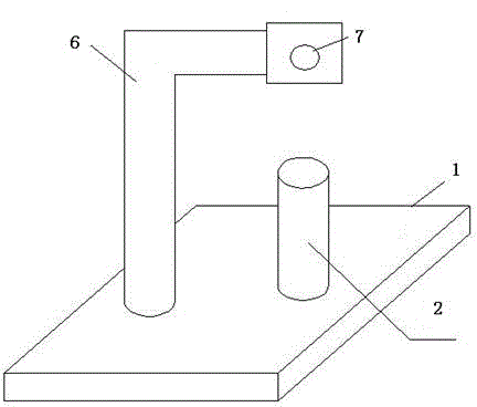
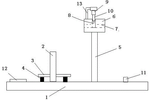
[0015] Such as figure 2 As shown, a wire frame capable of automatically cutting yarns includes a base 1 and a tray 3, a yarn seat 2 and a bracket 5 are arranged on the top surface of the base 1, the yarn seat 2 is a round rod, and the tray 3 There is a through hole matching the yarn seat 2 at the center, the tray 3 is set on the yarn seat 2 through the through hole, and several pressure sensors 4 are arranged on the top surface of the base 1 opposite to the bottom surface of the tray 3, and the pressure sensors 4 are uniform Setting, the pressure value induced by the pressure sensor 4 is displayed through the display screen 12. For the convenience of observation, the display screen 12 is arran...


PUM


Abstract

The invention discloses a yarn-guide rack capable of automatically cutting yarns. The yarn-guide rack comprises a base, the top surface of which is provided with a yarn seat and a support. The yarn seat is a circular rod. The top of the support is provided with a yarn-guide block. A transverse yarn-guide hole is formed in the yarn-guide block. The top surface of the yarn-guide block is provided with a vertical groove communicated with the yarn-guide hole. The top surface of the yarn-guide block is further provided with a fixing rack, on which an air cylinder is fixed. The end portion of the air cylinder faces towards a notch of the groove. The end portion of a telescopic rod of the air cylinder is fixed with a blade. The width of the blade is matched with the groove. The blade directly faces the groove and performs up-and-down motion in the groove under the drive of the air cylinder. The yarn-guide rack capable of automatically cutting yarns has following beneficial effects: when weaving operation is finished, the air cylinder drives the blade so that yarns penetrating through the yarn-guide hole can be cut; and yarns can be automatically cut without manual labor so that time is saved.

Description

technical field [0001] The invention relates to a lead frame, in particular to a lead frame capable of automatically cutting yarns. Background technique [0002] The finished yarn is generally wound on a cylindrical cylinder. When weaving, the yarn needs to be drawn out. The lead frame is a device to ensure that the yarn is drawn out in sequence. The existing lead frame such as figure 1 As shown, the base 1 is included, and the top surface of the base 1 is provided with a yarn seat 2 and a support 5. The yarn seat 2 is used to place a cylindrical cylinder, which is a round rod, and the top of the support 5 is provided with a wire Hole 7: Because at the end of weaving, the yarn needs to be cut, the existing lead frame needs to be cut manually, which is very time-consuming. Contents of the invention [0003] In order to solve the above technical problems, the present invention provides a lead frame capable of automatically cutting yarns. [0004] In order to achieve the ab...

Claims


Application Information

Patent Timeline
Patent Type & Authority Applications(China)
IPC IPC(8): B65H57/00
Inventor 刘俊麟李小明逯在峰
Owner ZHANGJIAGANG HUAYUAN DYEING & WEAVING
Why Eureka
Try Eureka