Block machine for construction

A block forming machine and construction technology, applied in the direction of conveyor objects, cleaning devices, supply devices, etc., can solve the problems of increasing the load of the roller drive motor, reducing the efficiency of the conveyor belt, and cannot be cleaned, so as to avoid belt scratches Injury, small footprint, cost-saving effect

Active Publication Date: 2015-09-09
河北技科新型建材制造有限公司
View PDF11 Cites 5 Cited by
  • Summary
  • Abstract
  • Description
  • Claims
  • Application Information

AI Technical Summary

Problems solved by technology

Because mortar is a viscous substance, it is easy to adhere to the belt surface of the belt conveyor during transportation. The mortar adhered to the working surface of the belt will increase the load of the drum drive motor, consume a lot of energy, and reduce the efficiency of the conveyor belt; therefore The mortar on the belt needs to be cleaned. At present, the mortar on the belt is generally cleaned manually. The efficiency of manual cleaning is low and accidents are prone to occur
There is also a scraper fixed at one end of the conveyor belt. When the belt passes the scraper, the mortar adhering to the belt is scraped off by the scraper. However, the cleaning effect of this method is not good, and the mortar adhering to the belt is often not cleaned. , and the scraped mortar cannot be collected, resulting in waste, and the mortar is spilled on the ground, polluting the working environment

Method used


Image

  • Block machine for construction
  • Block machine for construction
  • Block machine for construction

Examples


Embodiment Construction

[0014] The present invention will be further described below in conjunction with the accompanying drawings and embodiments, but not as a basis for limiting the present invention.

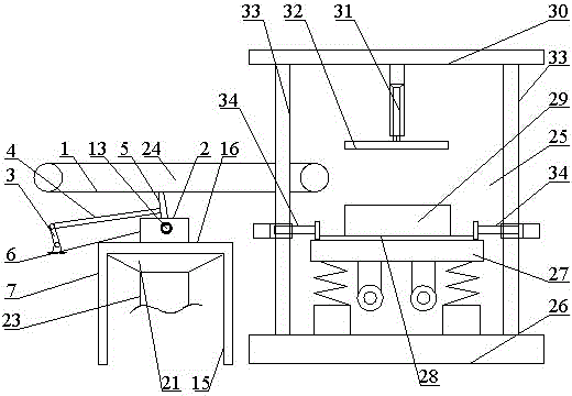
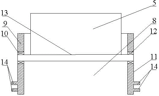
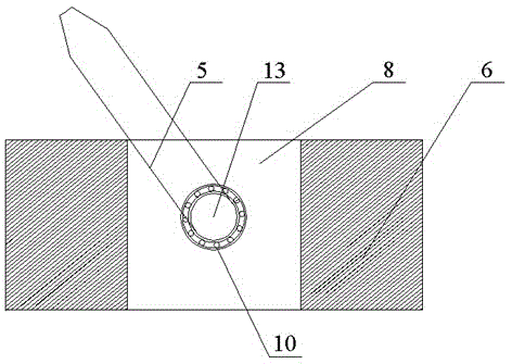
[0015] Example. A building block forming machine, constituted as Figure 1-6 Shown, comprise feeding device 24, and feeding device 24 is connected with frame 25; On the base plate 26 of described frame 25, vibrating device 27 is installed, and vibrating device 27 is provided with supporting plate 28, and mold 29 is placed on supporting plate 28 , the beam 30 of the frame 25 is provided with a first oil cylinder 31, the first oil cylinder 31 is connected with the pressure head 32, the column 33 of the frame 25 is provided with a second oil cylinder 34, and the position of the second oil cylinder 34 corresponds to the supporting plate 28 ; The feeding device 24 includes a conveyor belt 1, and a cleaner 2 is provided below the conveyor belt 1; Connected with the slider 6, the slider 6 is movably con...


PUM


Abstract

The invention discloses a block machine for construction. The block machine for construction comprises a feeding device connected with a rack. A jolt ramming device is installed on a bottom board of the rack. A die is placed on a carrying board of the jolt ramming device. A first oil cylinder on a beam of the rack is connected with a pressing head. A second oil cylinder on an upright of the rack corresponds to the carrying board in position. A sweeping device is arranged below a conveyor belt of the feeding device. A crank of the sweeping device is connected with a rocker. The rocker is connected with a scraper. The scraper is connected with a sliding block. The sliding block is movably connected with a support. A shaft is arranged in a cavity of the sliding block and connected with the scraper. Protrusions are arranged on the outer side of the cavity. A top board is arranged at the top of the upright of the support. Guide rails are arranged on the inner side of a square cavity of the top board. A collection cavity of the top board is connected with the support and is conic. The collection cavity is connected with a conveying pipe. Mortar adhering to the conveyor belt of the block machine can be well removed, the removed mortar can be collected, waste is avoided, labor cost is low, and efficiency is high.

Description

technical field [0001] The invention relates to a building forming machine, in particular to a building block forming machine. Background technique [0002] When building blocks are formed, the mortar is usually transported to the mold by a belt conveyor, and then compacted with a pressure head to form a formed block. Because mortar is a viscous substance, it is easy to adhere to the belt surface of the belt conveyor during transportation. The mortar adhered to the working surface of the belt will increase the load of the roller drive motor, consume a lot of energy, and reduce the efficiency of the conveyor belt; therefore The mortar on the belt needs to be cleaned. At present, manual cleaning of the mortar on the belt is generally used. The efficiency of manual cleaning is low and accidents are prone to occur. There is also a scraper fixed at one end of the conveyor belt. When the belt passes the scraper, the mortar adhering to the belt is scraped off by the scraper. Howev...

Claims


Application Information

Patent Timeline
Patent Type & Authority Applications(China)
IPC IPC(8): B65G45/12B65G45/26B28B13/02
Inventor 沈文宝童小燕
Owner 河北技科新型建材制造有限公司
Why Eureka
Try Eureka