Compound braking method
A compound braking and electric braking technology, which is applied in electric braking systems, electric vehicles, transportation and packaging, etc., can solve the problems of poor braking sensitivity and achieve high braking comfort, smooth braking, and high braking sensitivity. Good results
- Summary
- Abstract
- Description
- Claims
- Application Information
AI Technical Summary
Problems solved by technology
Method used
Image
Examples
Embodiment 1
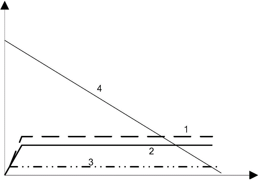
[0033] A composite braking method, the composite braking force is equal to the sum of the electric braking force and the frictional braking force, the braking is performed according to the braking demand of the vehicle, and the composite braking force remains unchanged.
[0034] The technical means involved in the above technical solution will be described in detail below in conjunction with the accompanying drawings.
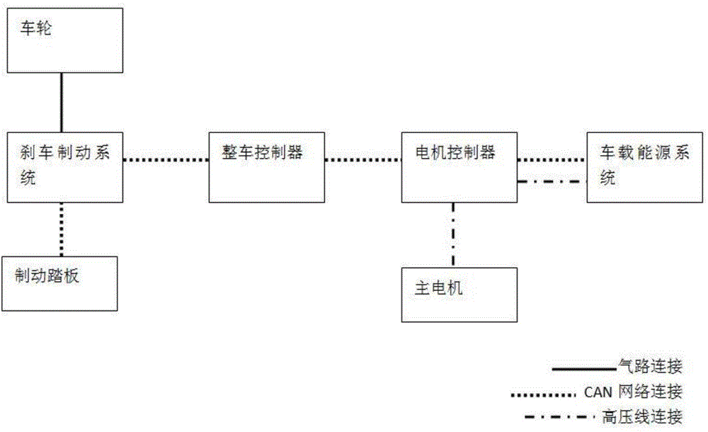
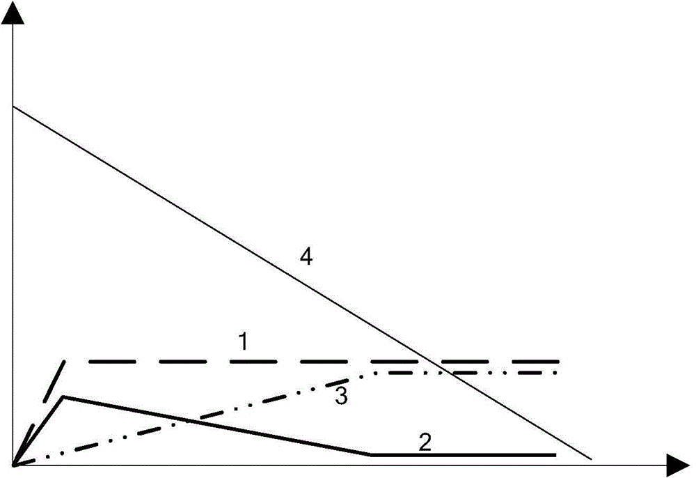
[0035] Such as figure 2 Shown is a schematic structural diagram of the composite braking system, and the vehicle controller simultaneously controls and connects the braking system and the motor controller. When a general hybrid vehicle brakes according to the braking requirements of the vehicle, its braking is mostly compound braking, which includes electric braking and friction braking, such as image 3 As shown, among them: electric braking is to feed back the energy of wheel rotation to the on-board energy system to achieve the purpose of braking, and fric...
Embodiment 2
[0037] Continue to elaborate on the basis of Example 1.
[0038] On the premise that the composite braking force remains unchanged, when braking starts, increase the frictional braking force to the first set value, then gradually decrease the frictional braking force, and gradually increase the electric braking force.
[0039] The technical means involved in the above technical solution will be described in detail below in conjunction with the accompanying drawings.
[0040] Such as image 3 As shown, when the vehicle is combined braking, the compound braking force is first distributed to the frictional braking force, and the frictional braking force rises to a certain value in a short time, then the frictional braking force gradually decreases, and the electric braking force gradually increases. During braking, the compound braking force remains unchanged.
[0041] At the beginning of braking, since the braking force is achieved by depressing the brake pedal, depressing the...
Embodiment 3
[0055] The difference between this embodiment and Embodiment 2 is that when the frictional braking force gradually decreases and the electric braking force gradually increases, it decreases or increases nonlinearly, for example, it changes according to a certain curve, but the overall The braking force remains unchanged, such as Figure 6 shown.
PUM
 Abstract
Description
Claims
Application Information
 - Generate Ideas
- Intellectual Property
- Life Sciences
- Materials
- Tech Scout
- Unparalleled Data Quality
- Higher Quality Content
- 60% Fewer Hallucinations
Browse by: Latest US Patents, China's latest patents, Technical Efficacy Thesaurus, Application Domain, Technology Topic, Popular Technical Reports.
© 2025 PatSnap. All rights reserved.Legal|Privacy policy|Modern Slavery Act Transparency Statement|Sitemap|About US| Contact US: help@patsnap.com


