a silage machine

A technology of silage machine and rack, applied in the field of silage machine, can solve the problems of single function of agricultural machinery, very broken corn stalk powder, labor-intensive and time-consuming, etc., to save time and labor, reduce maintenance costs, and large maintenance space. Effect

Inactive Publication Date: 2017-03-22
张雄磊
View PDF7 Cites 0 Cited by
  • Summary
  • Abstract
  • Description
  • Claims
  • Application Information

AI Technical Summary

Problems solved by technology

[0002] With the development of science and technology and the continuous improvement of farmers' living standards, agricultural machinery products have been widely used in agricultural production, and the varieties and functions of agricultural machinery are also becoming more and more diversified. However, in actual agricultural production, some of the agricultural machinery The function is still relatively simple
For example, when it is necessary to collect and crush corn and corn stalks for feed or fertilizer, it is necessary to use a corn combine harvester to harvest the corn and corn stalks first, and then transport them to the field for crushing, which is labor-intensive and time-consuming. increase the labor force of farmers
The rotary axis of the dial wheel at the front end of the existing silage machine is all set horizontally. The corn stalks received in the header of such a silage machine are all messy, and there are both horizontal and vertical. In this way, the guillotine wheel cannot guarantee that each cornstalk will The corn stalks are very crushed, which greatly affects the crushing effect of the corn stalks

Method used


Image

  • a silage machine
  • a silage machine
  • a silage machine

Examples


Embodiment Construction

[0024] The silage machine of the present invention will be further described below in conjunction with the accompanying drawings and specific embodiments:

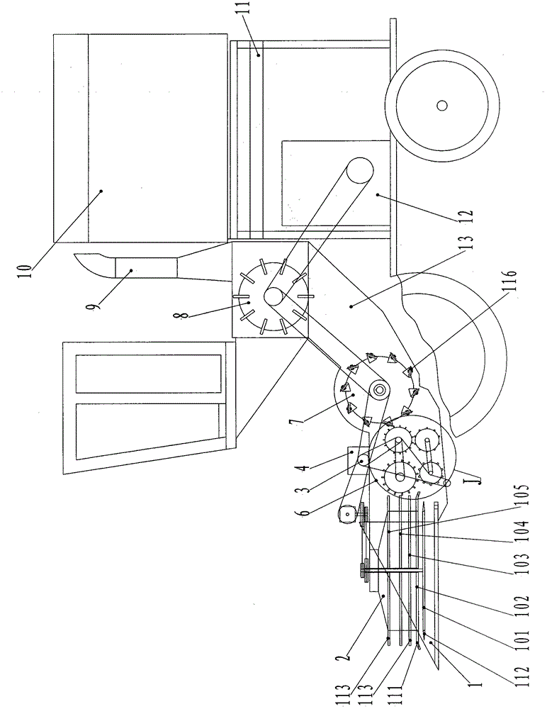
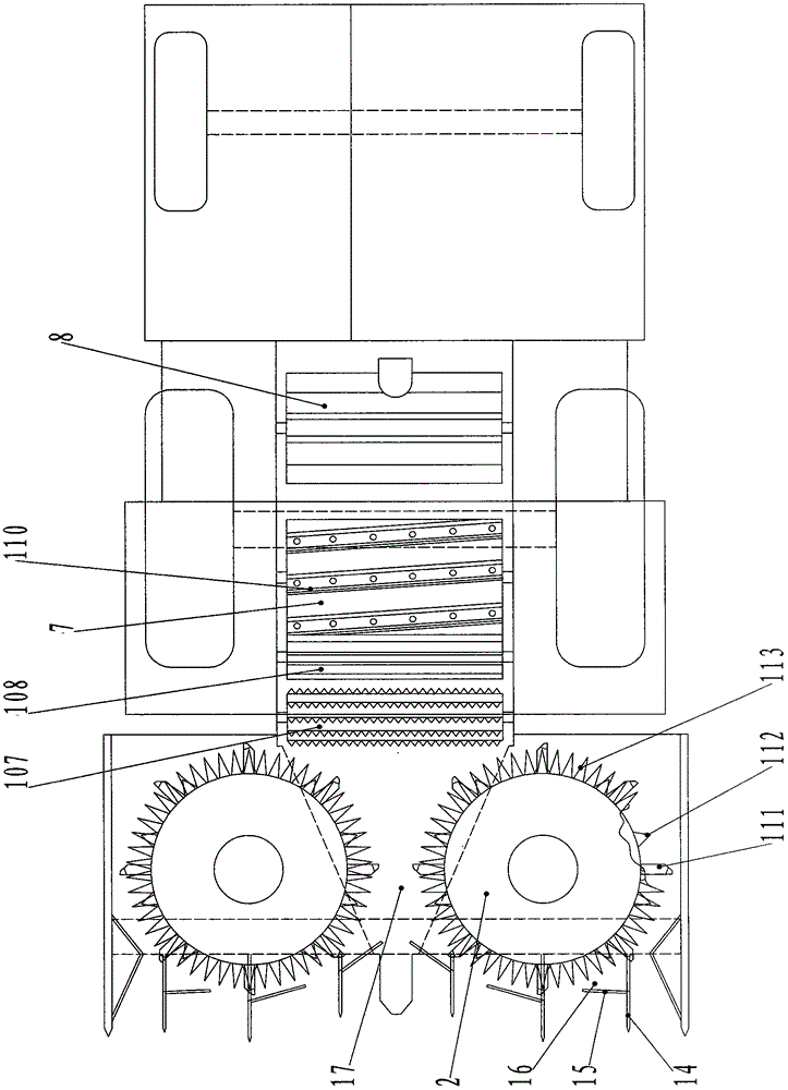
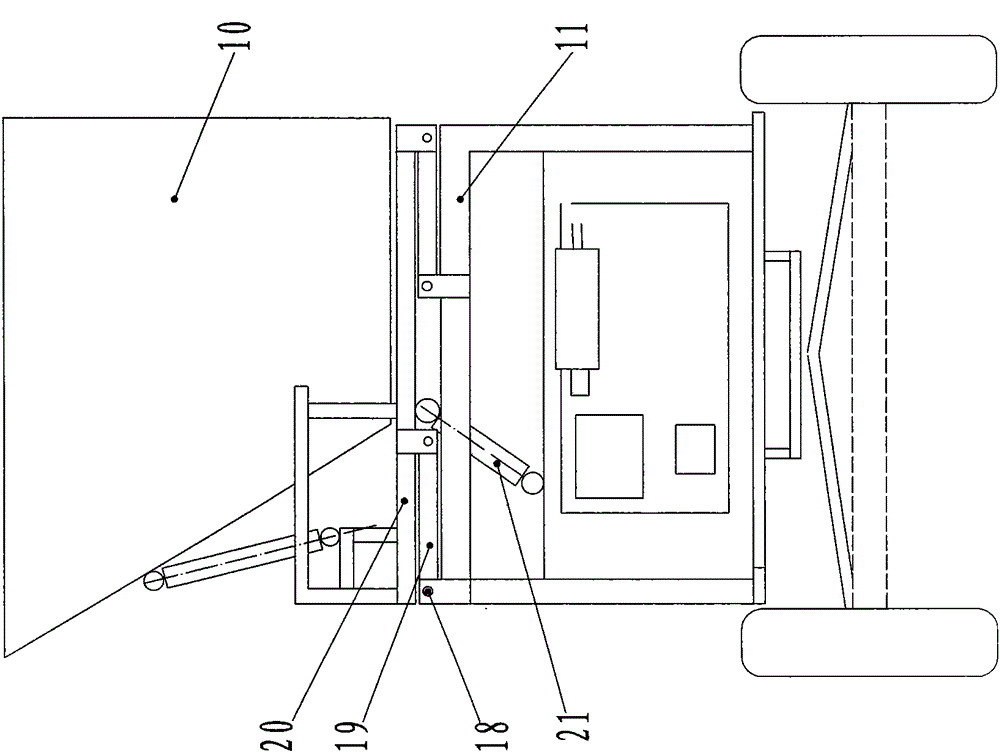
[0025] figure 1 It is a structural schematic diagram of a silage machine of the present invention, figure 2 yes figure 1 top view of Figure 4 yes figure 1 Zoomed-in view at middle J, Figure 5 yes Figure 4 The top view of middle part 106 and part 109, in the figure, this silage machine, comprises frame 11, is arranged on the feed bin 10 on frame 11 and the header 1 of frame 11 front ends, and frame 11 is provided with engine 12, The rear end of the header 1 is connected to the feeding box 13, and the upper end of the feeding box 13 is provided with a discharge cylinder 9. On the header 1, two cutter dials 2 with opposite directions of rotation are arranged side by side, and two cutter dials 2 The axis of rotation is vertically arranged, and the cutter dial 2 is provided with a multi-layer dial, and the following o...


PUM


Abstract

The invention discloses a silage harvester comprising a frame, a feed bin arranged on the frame and a cutting table arranged at the front end of the frame. An engine is arranged on the frame, the rear end of the cutting table is connected with a conveying box, a discharge cylinder is arranged at the upper end of the conveying box, two cutter star wheels opposite in rotation direction are arranged on the cutting table side by side, rotation axes of the cutter star wheels are arranged vertically, a conveying channel is arranged between the cutter star wheels, the conveying channel is connected with an inlet of the conveying box, a front group of conveying wheels and a rear group of conveying wheels are arranged at the inlet of the conveying box, each group of conveying wheels is arranged vertically, the upper conveying wheels and the lower conveying wheels are opposite in turning direction, a chopping cutting wheel is arranged behind the conveying wheels, and a blowing wheel is arranged at the outlet of the conveying box. The silage harvester is compact in structure, uniform in smashing, high in operation efficiency and low in maintenance cost, corn stalk is conveyed through the conveying wheels, and the problem that a chain is easily broken due to chain conveying of the original silage harvester is solved.

Description

technical field [0001] The present invention relates to an agricultural machine, more particularly to a silage machine. Background technique [0002] With the development of science and technology and the continuous improvement of farmers' living standards, agricultural machinery products have been widely used in agricultural production, and the varieties and functions of agricultural machinery are also becoming more and more diversified. However, in actual agricultural production, some of the agricultural machinery The function is still relatively simple. For example, when it is necessary to collect and crush corn and corn stalks for feed or fertilizer, it is necessary to use a corn combine harvester to harvest the corn and corn stalks first, and then transport them to the field for crushing, which is labor-intensive and time-consuming. increase the labor force of farmers. The rotary axis of the dial wheel at the front end of the existing silage machine is all set horizon...

Claims


Application Information

Patent Timeline
Patent Type & Authority Patents(China)
IPC IPC(8): A01D43/08A01D57/22A01D57/02
Inventor 张雄磊
Owner 张雄磊
Why Eureka
Try Eureka