
In-mold detachable stamping device

A marking device, technology in the mold, applied in the field of marking devices, can solve the problems of time-consuming, low maintenance work efficiency, troublesome disassembly work, etc.

Active Publication Date: 2015-09-02
URATANISHOJI
View PDF5 Cites 2 Cited by
  • Summary
  • Abstract
  • Description
  • Claims
  • Application Information

AI Technical Summary

Problems solved by technology

This dismantling is cumbersome and time-consuming, therefore, the efficiency of maintenance work is very low

Method used


Image

  • In-mold detachable stamping device
  • In-mold detachable stamping device
  • In-mold detachable stamping device

Examples


Embodiment Construction

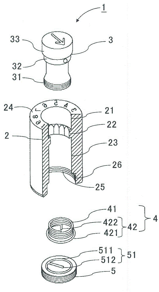
[0036] Hereinafter, embodiments of the in-mold detachable marking device of the present invention will be explained with reference to the accompanying drawings. figure 1 is an exploded perspective view showing the in-mold detachable marking device of the present invention.

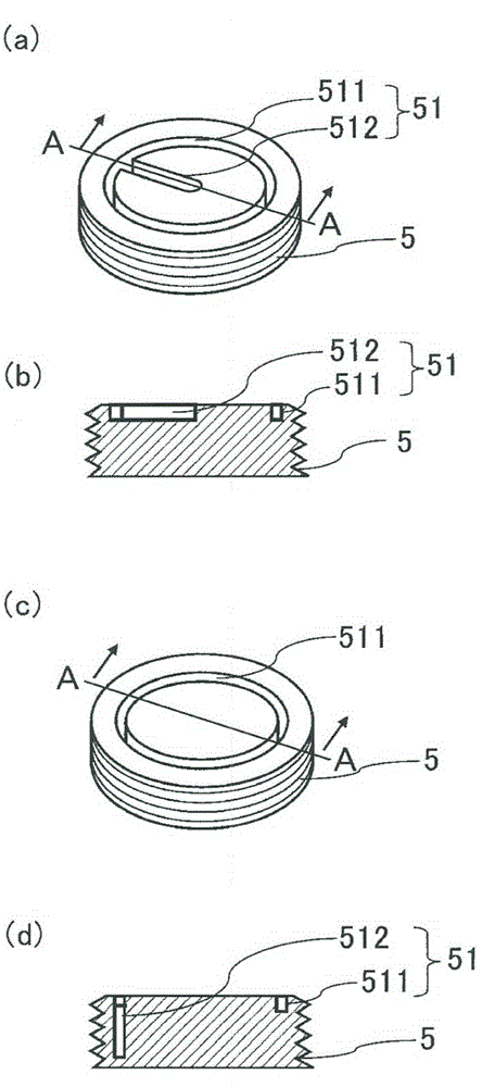
[0037] The in-mould detachable marking device 1 of the present invention (hereinafter referred to as marking device 1 ) comprises a substantially cylindrical outer housing 2 for indication, fitted to the above-mentioned outer housing 2 for indication and configured to surround the The indicating body 3 with the axis of the indicating outer housing angularly moving, the cover 5 screwed to the bottommost 26 of the indicating outer housing 2 , and the spring 4 biasing the indicating body 3 with a downward force.

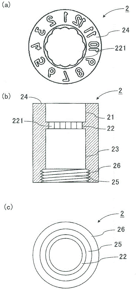
[0038] The inner wall surface 2 of the outer housing for indication is divided into three regions; the upper section 21 receives the marking section 3, the middle section 22 is located below the up...


PUM


Abstract

[Problem] To provide an in-mold detachable stamping device, in which rotation of the indicator does not lock even after repeated rotation to change the stamp mark. [Solution] A stamping device: which is provided with a roughly cylindrical outer marking shell that is fitted into a shaping mold, an indicator that is fitted inside said outer marking shell and is capable of angular displacement around the axial line, a cover that screws onto the lowermost section of the outer marking shell, and a spring for biasing the indicator with a downward force; and in which the stamp marking section is formed on surfaces of the outer marking shell and the indicator. The in-mold detachable stamping device is characterized in that: the indicator is provided with an indicator section that faces onto the inner surface of the mold, a positioning section extending downward from the indicator section, and a shaft section extending downward from the positioning section; the shaft section has a threaded part at the lower end; the spring has an engaging section that engages with the indicator and a fixing section that is fixed to the cover; the pitch of the spring in the engaging section and the pitch of the threaded section are equal; and the engaging section is engaged with the threaded section.

Description

technical field [0001] The present invention relates to a marking device for marking on a molded surface as the mold is being formed, and in particular to an in-mold removable marking device which does not lock the rotation of the marking body even if the marking body is repeatedly Turn to switch the marker indication. Background technique [0002] The date of manufacture, lot number, product number, etc. are usually provided on the molding surface, and these indications are used for researching causes of defects in molding and for inventory control. The indicating body includes a marker indicating portion, which is attachably and detachably inserted into an inner surface of a molding die, and then molded as the indicating body is inserted thereinto. As a result, these instructions (completely including the marking content of the instruction body) are marked and shaped on the molding surface. [0003] Patent Document 1 discloses a marking device including such an indicatin...

Claims


Application Information

Patent Timeline
Patent Type & Authority Applications(China)
IPC IPC(8): B29C33/42
CPCB29C45/374B29C33/428
Inventor 浦谷英树
Owner URATANISHOJI
Learn More