
Multi-power switching circuit and anesthesia machine with it

A multi-power switching and circuit technology, which is applied to circuit devices, emergency power arrangements, electrical components, etc., can solve problems such as increased power consumption and heat generation, and achieve the effects of low power consumption, reverse flow, and strong flow capacity

Active Publication Date: 2018-11-13
BEIJING AEONMED
View PDF7 Cites 0 Cited by
  • Summary
  • Abstract
  • Description
  • Claims
  • Application Information

AI Technical Summary

Problems solved by technology

This solution can solve the problem of continuous switching between different voltages of multiple power supplies, but when the power consumption of the system power supply is relatively large, this solution shows serious disadvantages of heating, specifically: the conduction voltage drop of the Schottky diode is between 0.35 and It is about 0.6V, and it will rise with the increase of current. The power consumption of Schottky diode is equal to the product of conduction voltage drop and conduction current. When the current exceeds 5A, its power consumption will increase significantly and the heat will be serious.

Method used


Image

  • Multi-power switching circuit and anesthesia machine with it
  • Multi-power switching circuit and anesthesia machine with it
  • Multi-power switching circuit and anesthesia machine with it

Examples


Embodiment Construction

[0023] Embodiments of the present invention are described in detail below, examples of which are shown in the drawings, wherein the same or similar reference numerals designate the same or similar elements or elements having the same or similar functions throughout. The embodiments described below by referring to the figures are exemplary and are intended to explain the present invention and should not be construed as limiting the present invention.

[0024] In describing the present invention, it should be understood that the terms "center", "longitudinal", "transverse", "length", "width", "thickness", "upper", "lower", "front", " Orientation or position indicated by "back", "left", "right", "vertical", "horizontal", "top", "bottom", "inner", "outer", "clockwise", "counterclockwise", etc. The relationship is based on the orientation or positional relationship shown in the drawings, and is only for the convenience of describing the present invention and simplifying the descrip...


PUM


Abstract

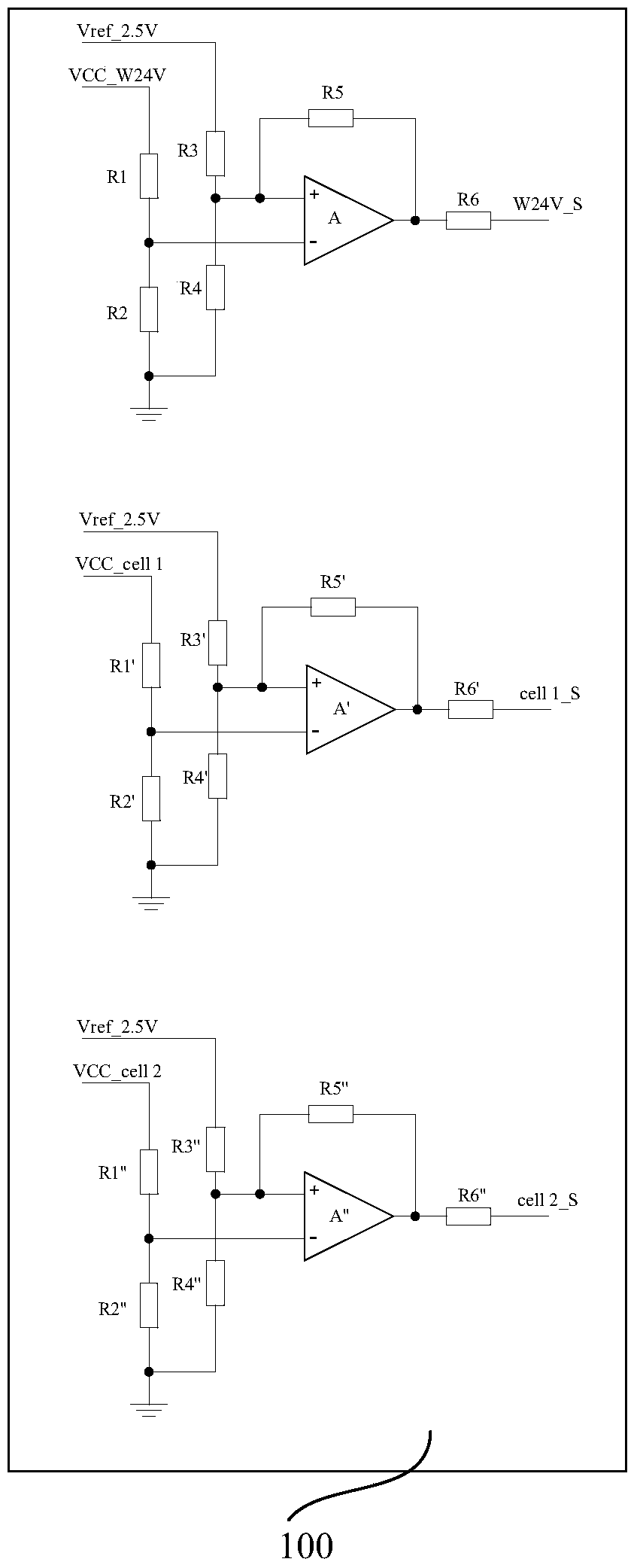
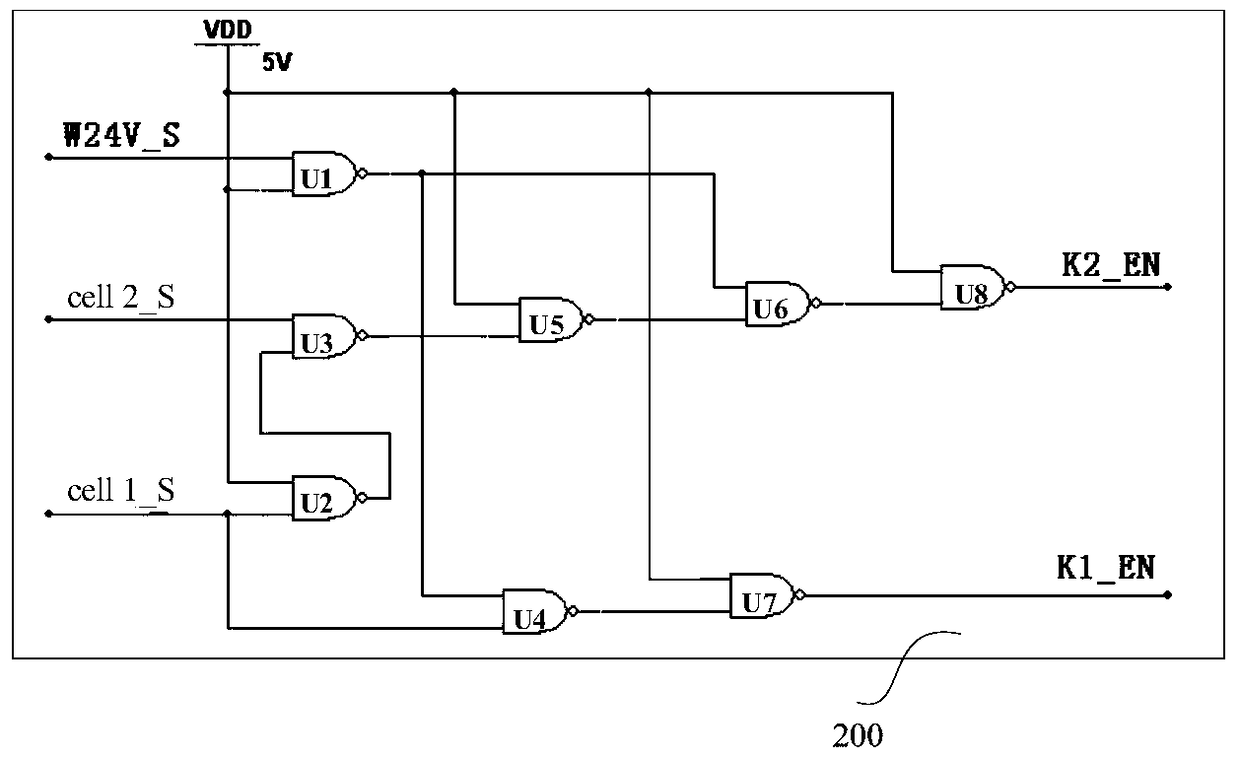
The invention discloses a multi-power switching circuit and an anaesthesia machine with the multi-power switching circuit. The multi-power switching circuit comprises a voltage sampling processing module connected to a main power source, a first auxiliary power supply and a second auxiliary power supply, and used for sampling voltage; a logic processing module used for outputting a first logic level signal and a second logic level signal according to a main power supply sampling signal, a first auxiliary power supply sampling signal and a second auxiliary power supply sampling signal; a level switch module used for converting a first logic level signal and a second logic level signal into converted matching signals matching a PMOS; a PMOS acceleration driving module used for performing acceleration driving on the converted matching signals; and a PMOS switch module used for outputting power. The multi-power switching circuit can realize automatic seamless switching among the main power source, the first auxiliary power supply and the second auxiliary power supply, and consume less power.

Description

technical field [0001] The invention belongs to the technical field of analog circuits, and in particular relates to a multi-power switching circuit and an anesthesia machine equipped with it. Background technique [0002] In order to prevent the operation from being interrupted due to power grid outages, medical and surgical equipment such as anesthesia machines often use multiple sets of backup power supplies to provide reliable guarantees. There are voltage differences in the power supply system of multiple groups of power supplies, and uninterrupted switching between different power supplies should be ensured. [0003] The current commonly used switching method mainly uses Schottky diodes as the "OR" relationship output of multiple sets of power supplies. This solution can solve the problem of continuous switching between different voltages of multiple power supplies, but when the power consumption of the system power supply is relatively large, this solution shows seri...

Claims


Application Information

Patent Timeline
Patent Type & Authority Patents(China)
IPC IPC(8): H02J9/06
Inventor 聂培军
Owner BEIJING AEONMED
Learn More