A complete set of equipment for relay protection configuration of power plant power system

A technology of relay protection device and factory power system, applied in emergency protection circuit devices, electrical components, etc., can solve problems such as equipment damage, failure of relay protection device to be quickly cut off, and no main protection for 6KV busbars. The effect of reliability

Active Publication Date: 2017-08-25
CHNA ENERGY INVESTMENT CORP LTD +2
View PDF2 Cites 0 Cited by
  • Summary
  • Abstract
  • Description
  • Claims
  • Application Information

AI Technical Summary

Problems solved by technology

[0007] The action time of the high-voltage overcurrent protection device Gg has reached 2.5s, which loses its protection significance for serious faults, which will cause serious damage to the equipment and expansion of the situation, and cannot meet the requirements of "rapidity and reliability" of relay protection.
[0008] (2) There is no main protection for the 6KV factory busbar: According to the regulations, the 6KV factory busbar of the power plant does not have a dedicated busbar protection, and the protection of the 6KV busbar is realized by the backup protection of the high-voltage factory transformer
[0010] (4) The main protection of the low-voltage industrial transformer has a dead zone: the main protection of the low-voltage industrial transformer is generally a current quick-break protection. Such a setting principle makes a small part of the low-voltage side body of the low-voltage industrial transformer and the contact wire before the low-voltage side outlet to the 400V bus incoming switch become the main protection dead zone. When a fault occurs in this section, only The fault can be cut off by the low-voltage overcurrent protection device Dg, and the time is usually relatively long (1.5s), which is likely to cause accident expansion and equipment damage
[0011] The above defects lead to the failure of the corresponding relay protection device to quickly remove the fault when a serious fault occurs in the power system of the plant, resulting in serious burnout of electrical equipment and huge losses

Method used


Image

  • A complete set of equipment for relay protection configuration of power plant power system
  • A complete set of equipment for relay protection configuration of power plant power system
  • A complete set of equipment for relay protection configuration of power plant power system

Examples


Embodiment Construction

[0019] Specific embodiments of the present invention will be described in detail below in conjunction with the accompanying drawings. It should be understood that the specific embodiments described here are only used to illustrate and explain the present invention, and are not intended to limit the present invention.

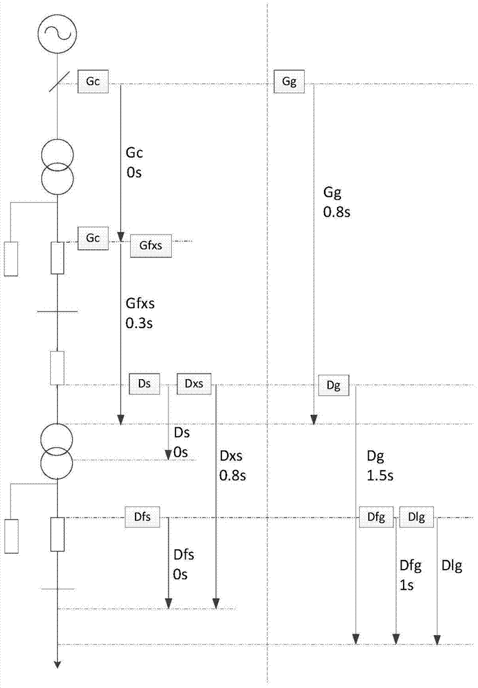
[0020] The complete set of device for relay protection configuration of power plant power system of the present invention comprises: high-voltage plant transformer relay protection device, which is set on the high-voltage side and / or low-voltage side of the high-voltage plant transformer of the power system; The transformer relay protection device is installed on the high-voltage side or low-voltage side of the low-voltage factory-use transformer of the power plant power system.

[0021] 1. The operating current of the high-voltage branch time-limited quick-break protection device Gfxs

[0022] Such as figure 2 As shown (wherein, the arrow indicates the prote...


PUM


Abstract

The present invention relates to the technical field of relay protection, and discloses a complete set of device for relay protection configuration of the power system of a power plant. The high-voltage side and / or low-voltage side of the high-voltage factory-use transformer of the power system; and the relay protection device of the low-voltage factory-use transformer, which is set on the high-voltage side or low-voltage side of the low-voltage factory-use transformer of the power plant power system; the high-voltage factory-use transformer The transformer relay protection device includes: a high-voltage branch time-limited quick-break protection device, which is installed on the branch of the low-voltage side of the high-voltage plant transformer, and is used as the main protection for the corresponding section of the busbar on the low-voltage side of the high-voltage plant transformer. When the current value of the quick-break protection device is greater than or equal to the operating current, the fault on the low-voltage side busbar of the high-voltage industrial transformer is removed. The complete relay protection configuration device of the present invention can quickly remove faults at corresponding positions in the electricity system of a power plant.

Description

technical field [0001] The invention relates to the technical field of relay protection, in particular to a complete set of device for relay protection configuration of a power system of a power plant. Background technique [0002] Various related regulations and specifications of relay protection (such as GB / T14285, DL / T5153, etc.) stipulate the basic principles of relay protection configuration of power plant power equipment. For a long time, the relay protection of plant power system is Carry out protection configuration design and setting calculation on the basis of adhering to these basic principles. Taking a 600MW unit as an example, the design scheme of the typical configuration of relay protection for utility power is shown in Table 1 and figure 1 Shown (wherein, the arrow indicates the scope of protection): [0003] Table 1 Typical configuration of relay protection for 600MW generating set plant power system [0004] [0005] However, for a long time, there ha...

Claims


Application Information

Patent Timeline
Patent Type & Authority Patents(China)
IPC IPC(8): H02H7/22
Inventor 李子峰
Owner CHNA ENERGY INVESTMENT CORP LTD
Why Eureka
Try Eureka