
Lamp support for mine shaft bottom

A light stand and mine technology, which is applied to lighting devices, lighting device parts, lighting auxiliary devices, etc., can solve the problems of poor light and inconvenient mining, and achieve the effect of convenient mining

Inactive Publication Date: 2015-09-02
李广连
View PDF5 Cites 0 Cited by
  • Summary
  • Abstract
  • Description
  • Claims
  • Application Information

AI Technical Summary

Problems solved by technology

The light at the bottom of the existing mine is poor, and mining is inconvenient

Method used


Image

  • Lamp support for mine shaft bottom
  • Lamp support for mine shaft bottom

Examples


Embodiment Construction

[0012] The preferred embodiments of the present invention will be described in detail below in conjunction with the accompanying drawings, so that the advantages and features of the present invention can be more easily understood by those skilled in the art, so as to define the protection scope of the present invention more clearly.

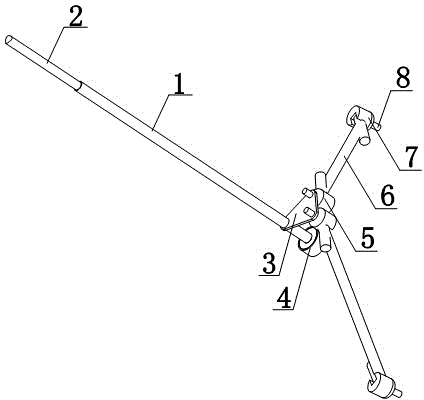
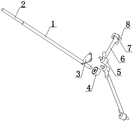
[0013] Such as figure 1 and figure 2 As shown, a mine bottom light stand includes a hanging rod 1, the end of the hanging rod 1 is provided with a hanging end 2, the lower end of the hanging rod 1 is provided with a fixing piece 3, and the fixing piece 3 is provided with a pair of connecting columns 5, which are connected Column 5 is provided with connecting rod 6, and the end of connecting rod 6 is provided with adjusting column 7, and the bottom of adjusting column 7 is provided with plunger 8;

[0014] The lamp holder at the bottom of the mine shaft of the present invention can install the lamp body at the position of the insertion rod 8, an...


PUM


Abstract

The invention discloses a lamp support for a mine shaft bottom, comprising a hanging rod. The end of the hanging rod is provided with a hanging end, the lower end of the hanging rod is provided with a fixing piece, the fixing piece is provided with a pair of joint pins, each joint pin is provided with a connecting rod, the end of each connecting rod is provided with an adjusting column, and the lower portion of each adjusting column is provided with an inserting rod. According to the lamp support, a lamp can be mounted at one of the inserting rods, horizontal rotating fine-adjustment of the connecting rods can be achieved by rotation around the fixing piece, thus the fine-adjustment of the lamp is facilitated and the lamp support can be installed at the mine shaft bottom to facilitate mining.

Description

technical field [0001] The invention relates to a lamp holder, in particular to a mine shaft bottom lamp holder. Background technique [0002] A mine mined underground. Sometimes the inclined shafts, shafts, and adits in the underground development of mines are also called mines. Mine development has a significant and far-reaching impact on the overall production and construction of metal mines or coal mines, and it is not only related to the amount of infrastructure work in mines. The light at the bottom of the existing mine shaft is poor, and mining is inconvenient. Contents of the invention [0003] The present invention mainly solves the technical problems existing in the prior art, thereby providing a lamp body that can be installed at the position of the insertion rod, and the horizontal rotation and fine adjustment can be realized around the fixed piece through the connecting rod, so as to facilitate the fine adjustment of the lamp body. The lamp holder is insta...

Claims


Application Information

Patent Timeline
Patent Type & Authority Applications(China)
IPC IPC(8): F21V21/22
CPCF21V21/22
Inventor 李广连
Owner 李广连
Learn More