
A prefabricated house and its construction method

A technology of prefabricated assembly and construction method, which is applied in the direction of structural elements, building components, and elongated structural components for load-bearing, etc. problem, to achieve the effect of good stress state, light structure, improved rigidity and axial direction

Active Publication Date: 2017-07-07
湖南愿景住宅工业科技有限公司
View PDF6 Cites 2 Cited by
  • Summary
  • Abstract
  • Description
  • Claims
  • Application Information

AI Technical Summary

Problems solved by technology

If a reinforced concrete frame or frame-shear structure is used, usually because the cross-sectional area of ​​the beams and columns is too large, it will occupy the actual use space and form "fat beams and columns"; moreover, this kind of "fat beams and columns" will make The use space of the house is irregular, which brings inconvenience to the residents
At the same time, because the solidification of concrete takes time, and it is not suitable for construction at low temperature, the construction speed of the building is limited.
Moreover, in traditional construction methods, a large amount of on-site construction work will cause pollution such as dust and noise, waste resources and energy, easily lead to safety accidents, and make quality control difficult
Steel structure buildings also have the following defects: 1. The fire resistance of steel structures is poor, and they are easy to collapse in case of fire; 2. During the service life of the building for one or two hundred years, the steel will also be corroded, and anti-corrosion issues need to be considered separately 3. The cost of steel structure is higher

Method used


Image

  • A prefabricated house and its construction method
  • A prefabricated house and its construction method
  • A prefabricated house and its construction method

Examples


Embodiment Construction

[0053] The present invention will be further described in detail below in conjunction with the accompanying drawings and specific embodiments.

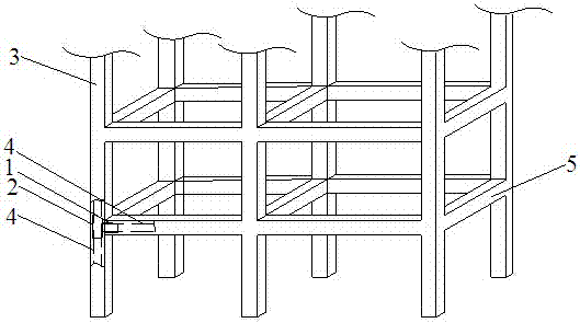
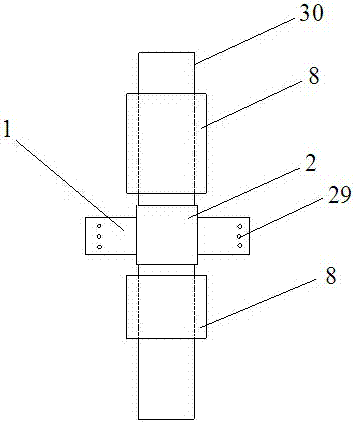
[0054] refer to figure 1 , figure 2 , this embodiment includes a house foundation, in which a foundation connector is pre-embedded, and a vertical prefabricated column is arranged on the foundation connector; refer to image 3 , Figure 4 , the prefabricated column 3 includes a prefabricated column rectangular steel pipe 30, the prefabricated column rectangular steel pipe 30 is filled with reactive powder concrete 7, except for the two ends of the prefabricated column rectangular steel pipe 30, the outside of the prefabricated column rectangular steel pipe 30 is wrapped with foamed cement 8; The prefabricated columns 3 are arranged vertically and horizontally, and the prefabricated columns 3 in the same vertical direction are superimposed one after another. Horizontal prefabricated beams 5 are installed between the tops of the adja...


PUM


Abstract

The invention provides a prefabricated house and a construction method thereof. The house comprises a house foundation, wherein a foundation connecting piece is embedded in the house foundation; the foundation connecting piece is provided with vertical precast columns; the precast columns are arrayed vertically and horizontally; the precast columns in the same vertical direction are sequentially superposed; horizontal precast beams are arranged among the tops of the adjacent precast columns in the same layer so as to form a house frame; the house frame consists of multiple unit layers; each unit layer comprises multiple unit rooms; <0}{0><}0{>the precast beams in each unit layer are provided with precast prestressed concrete composite floor slabs; anchor bars at two ends of the precast prestressed concrete composite floor plates are fixedly connected with floor slab connecting pieces reserved on the precast beams; vertical precast partition plates are arranged among the adjacent unit rooms; the outer side of the house frame is provided with a precast large out-hung panel; a precast stair plate is arranged between every two upper and lower unit layers. <0}{0><}0{>The construction method is capable of improving the use area of the house, and the prefabricated house is low in construction cost and good in fire resistance.

Description

technical field [0001] The invention relates to the field of construction, in particular to a prefabricated house and a construction method thereof. Background technique [0002] In the construction of high-rise and super high-rise buildings, the traditional construction method is on-site construction, and reinforced concrete frame or frame-shear structure can be used; in addition, there are very few steel structures. If a reinforced concrete frame or frame-shear structure is used, usually because the cross-sectional area of ​​the beams and columns is too large, it will occupy the actual use space and form "fat beams and columns"; moreover, this kind of "fat beams and columns" will make The use space of the house is irregular, which brings inconvenience to the residents. At the same time, because the solidification of the concrete takes time, and it is not suitable for construction at low temperature, the construction speed of the building is limited. Moreover, in traditio...

Claims


Application Information

Patent Timeline
Patent Type & Authority Patents(China)
IPC IPC(8): E04B1/19E04C3/36E04C3/293E04B1/58E04G21/14
Inventor 欧阳忠凯谢新林
Owner 湖南愿景住宅工业科技有限公司
Learn More