Flux-gate type non-contact current measuring device

A current measuring device, non-contact technology, applied in the direction of measuring device, only measuring current, using DC to AC conversion for measurement, etc., can solve the problems of trouble, detection of DC component, large deviation of magnetic core error rate, etc. To achieve the effect of convenience of use, elimination of saturation, and avoidance of mistakes

Inactive Publication Date: 2015-08-26
李尚哲
View PDF7 Cites 16 Cited by
  • Summary
  • Abstract
  • Description
  • Claims
  • Application Information

AI Technical Summary

Problems solved by technology

Therefore, the time constant varies with the magnetic properties of the core, and as a result, the core cannot be fully magnetized due to the application of a fixed-frequency oscillating signal that does not reflect the magnetic properties of the core, reducing the accuracy of current measurement
In order to overcome the above deficiencies, it is necessary to generate an oscillating signal that conforms to the magnetic characteristics of the magnetic core. However, due to the large error rate deviation of the magnetic core when making the current measuring instrument, it is difficult to make the circuit components that generate the oscillating signal suitable for the magnetic core, and it needs to be adjusted one by one. The current measuring instrument produced is not only troublesome, but also increases production efficiency and performance
[0007] In particular, in the prior art described above, in order to provide the magnetic cores on both sides with opposite polarities, the coils are connected in series (parallel when viewed from the connection node connected for inputting the oscillation signal), and then the oscillation signal is applied to the series connection of the two coils. node, so that the cores on both sides are magnetized in opposite directions, so just a small error in magnetization on both cores can cause a huge deviation in detection performance
[0008] At the same time, the above-mentioned prior art intends to magnetize the magnetic cores on both sides through the oscillating signal, but the measured current flowing in the wire also magnetizes the magnetic cores on both sides, and if the measured current is large, the magnetic cores will be damaged at the initial stage of detection. It will be saturated, and will oscillate at a high frequency much higher than the frequency of the vibration signal, so that the DC component cannot be detected by the fluxgate method

Method used


Image

  • Flux-gate type non-contact current measuring device
  • Flux-gate type non-contact current measuring device
  • Flux-gate type non-contact current measuring device

Examples


Embodiment Construction

[0028] The preferred embodiments of the present invention will be described in detail below in conjunction with the accompanying drawings, so that those skilled in the art can easily implement them.

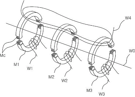
[0029] Figure 1 to Figure 4 It is a drawing for explaining an embodiment of a fluxgate type non-contact current measuring device of the present invention. figure 1 is a schematic diagram of the structure, figure 2 is a schematic diagram of the structure of a magnetic core wound with a coil, image 3 is the circuit diagram, Figure 4 It is a voltage waveform diagram of a current applied to magnetize the first magnetic core M1 and the second magnetic core M2.

[0030]The fluxgate type non-contact current measuring device of the present invention includes: three magnetic cores M1, M2, M3 that can respectively wind the wire W0 carrying the measured flowing current (the internal middle hole is through, so that the wire can pass through the magnetic core) ; Coils W1, W2, W3 wound...


PUM


Abstract

The present invention relates to a flux-gate type non-contact current measuring device for measuring a current to be measured by detecting an electromagnetic field around a conducting wire into which the current to be measured flows, wherein the present invention can detect a direct current component through a change of an oscillating signal by applying the oscillating signal for magnetizing two cores in mutually opposite polarities, wherein: an LC oscillation circuit is formed by using the inductance of a coil wound on one core, and the direct current component is detected by applying an LC-oscillating signal to a coil wound on the other core; an alternating current component is detected by using another core; compensated currents corresponding to the detected direct current and alternating current components are converged under a condition of offsetting a magnetic flux by the current to be measured, so that the current to be measured can be measured by measuring the compensated currents in the converged state thereof; and the present invention can normally measure a current by automatically demagnetizing an LC oscillating core even in a circumstance that the LC oscillating core is saturated by the current to be measured.

Description

technical field [0001] The present invention relates to a fluxgate type non-contact current measuring device that measures current by detecting an electromagnetic field around a wire in which current flows, and in particular, applies an oscillating signal that magnetizes two magnetic cores in opposite polarities, passing the oscillating signal The change of the DC component is detected by using the inductance of the coil wound on one of the magnetic cores to form an LC oscillation circuit, and the LC oscillation signal is applied to the coil wound on the other magnetic core to detect the DC component, and another magnetic core is used to detect the DC component. Detect the AC component, under the condition of offsetting the magnetic flux generated by the measured current, converge the compensation current corresponding to the detected DC and AC components, and detect the measured current by measuring the compensation current in this state, even if the LC oscillating magnetic I...

Claims


Application Information

Patent Timeline
Patent Type & Authority Applications(China)
IPC IPC(8): G01R15/20
CPCG01R15/185G01R19/20G01R15/20G01R19/0092
Inventor 李尚哲
Owner 李尚哲
Why Eureka
Try Eureka