A sound cavity rubber product

A sound chamber and product technology, applied in the direction of the microphone port/microphone accessories, etc., can solve the problems of no processing, poor sound effect on the receiver side, weakened sound intensity, etc., to avoid the loss of sound wave scattering, low development cost, and development cycle. short effect

Active Publication Date: 2018-10-16
苏州佳值电子工业有限公司
View PDF4 Cites 0 Cited by
  • Summary
  • Abstract
  • Description
  • Claims
  • Application Information

AI Technical Summary

Problems solved by technology

[0002] With the rapid development of electronic products, notebook computers, mobile phones, pads, etc. are more and more widely used, and their functions are becoming more and more abundant. Regarding the sound effects of microphones, there is also a demand for higher performance in the market, because when users use electronic When the product makes a call without earphones, there will be a certain distance between the head and the computer microphone. If the product mechanism is not properly designed, this distance will weaken the original sound and add noise from the surrounding environment, making the receiver's sound effect very poor
[0003] At present, there are two situations: the first one is mainly seen in low-end products, that is, if there is no treatment between the case and the microphone, the above-mentioned problems will occur; the second one is to use foam to fill the machine The gap between the shell and the microphone, but because the foam is a foam material, the material itself has many hollow air bubbles, which will absorb part of the sound waves, making the sound intensity weaken, and the foam is a die-cut material, the mechanism On the one hand, it can only be designed straight up and down, which limits its use in the institutional environment. In the end, the fire rating of general foam can only reach UL94-HF, and its performance is poor.

Method used


Image

  • A sound cavity rubber product
  • A sound cavity rubber product
  • A sound cavity rubber product

Examples


Embodiment Construction

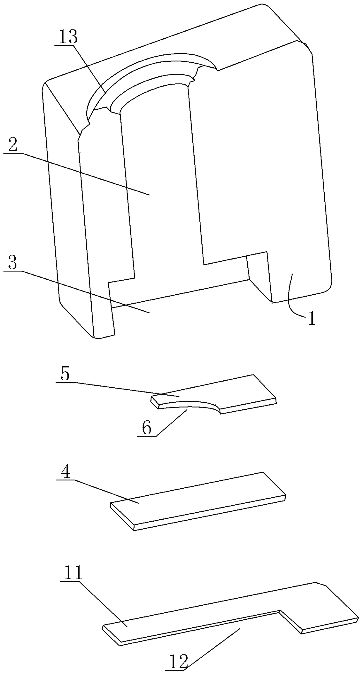
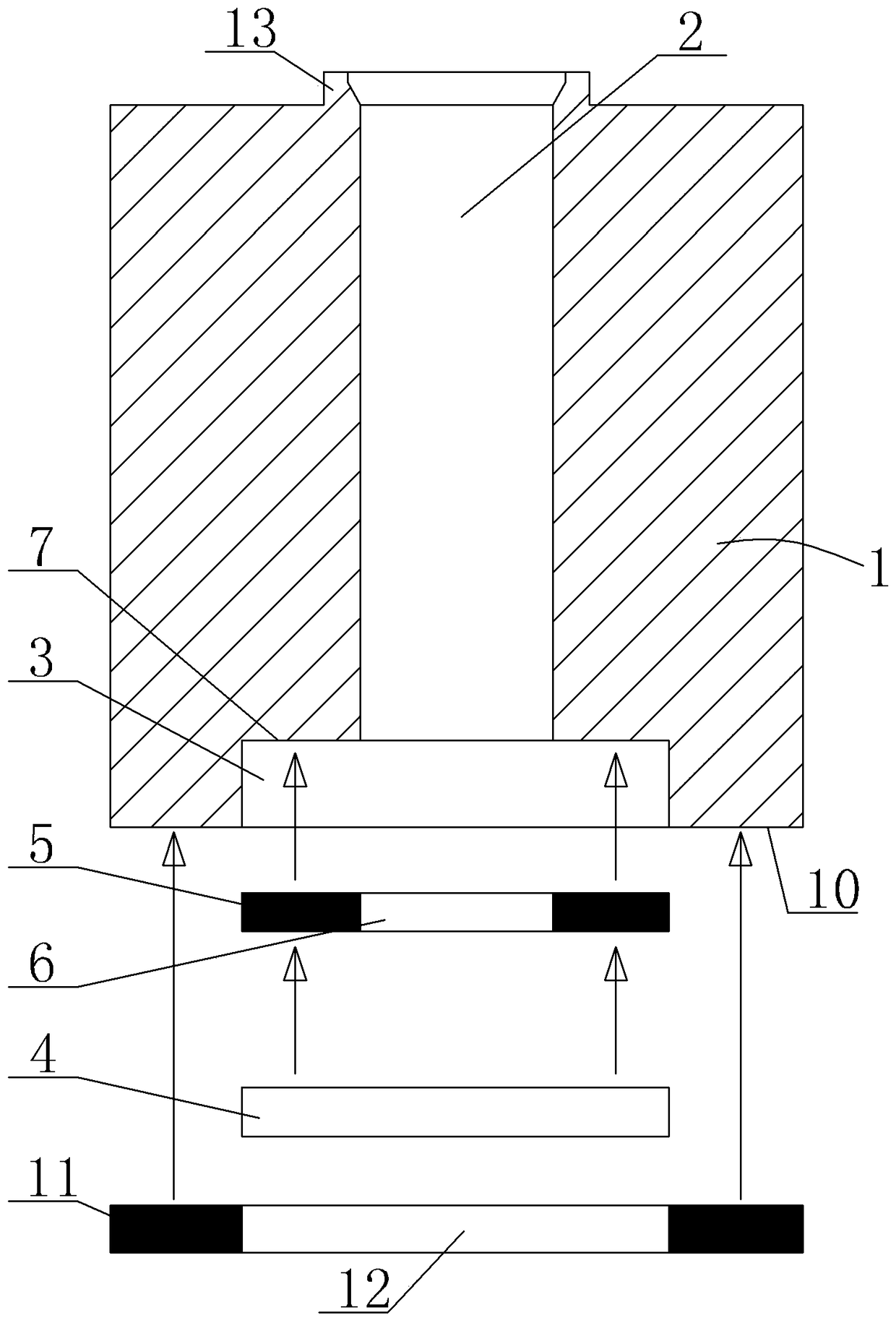
[0021] A sound cavity rubber product, see Figure 1 to Figure 4 : It includes a rubber body 1, the two sides of the rubber body 1 are designed according to the shape of the parts to be contacted, the rubber body 1 is formed by injection molding, the cavity shape of the mold determines the shape of the two sides of the rubber body 1, the shape of the mold The shape of the cavity is designed according to the shape of the part to be contacted, so that the end faces on both sides of the rubber body are respectively close to the corresponding parts to be contacted. The inside of the rubber body 1 is provided with a sound transmission cavity 2 connected on both sides, and the center of one side of the rubber body 1 Part of the recess forms the installation cavity 3, the sound transmission cavity 2 is connected to the installation cavity 3, the cross-sectional surface of the installation cavity 3 covers the cross-sectional surface of the sound transmission cavity 2, the installation c...


PUM


Abstract

The invention provides a sound chamber rubber product, which not only is low in cost, but also provides excellent sound receiving performance, excellent tone tuning performance, excellent buffer performance and excellent fireproof performance for an electronic product. The sound chamber rubber product comprises a rubber main body. End faces located at two sides of the rubber main body are arranged according to the shape of a part to be contacted and are tightly close to the corresponding part to be contacted respectively. A sound transmitting chamber whose two sides are communicated with each other are arranged in the rubber main body. A central part located at one side of the rubber main body is concaved inwardly to form an installing chamber. The sound transmitting chamber is communicated with the installing chamber. A transversal surface of the installing chamber covers a transversal surface of the sound transmitting chamber. Tone tuning paper is arranged in the installing chamber. The sound transmitting chamber is vertical to the surface of the tone tuning paper.

Description

technical field [0001] The invention relates to the technical field of the microphone sound effect structure of electronic products, in particular to a sound cavity rubber product. Background technique [0002] With the rapid development of electronic products, notebook computers, mobile phones, pads, etc. are more and more widely used, and their functions are becoming more and more abundant. Regarding the sound effects of microphones, there is also a demand for higher performance in the market, because when users use electronic When the product makes a call without earphones, there will be a certain distance between the head and the computer microphone. If the product mechanism is not properly designed, this distance will weaken the original sound and add noise from the surrounding environment, making the receiver's sound effect very bad. [0003] At present, there are two situations: the first one is mainly seen in low-end products, that is, if there is no treatment betwe...

Claims


Application Information

Patent Timeline
Patent Type & Authority Patents(China)
IPC IPC(8): H04R1/08
Inventor 李云涛
Owner 苏州佳值电子工业有限公司
Why Eureka
Try Eureka