
Backup power self-transfer protection system

A backup power self-switching and protection system technology, applied in the field of distribution network, can solve problems such as flickering, achieve the effects of avoiding flickering, improving user experience, and simplifying the structure

Active Publication Date: 2018-09-18
STATE GRID CORP OF CHINA +1
View PDF4 Cites 0 Cited by
  • Summary
  • Abstract
  • Description
  • Claims
  • Application Information

AI Technical Summary

Problems solved by technology

[0011] The main purpose of the present invention is to provide a protection system for automatic switching of backup power supply to solve the problem of flickering during low-voltage self-recovery of the automatic switching device for standby power supply in the prior art

Method used


Image

  • Backup power self-transfer protection system
  • Backup power self-transfer protection system
  • Backup power self-transfer protection system

Examples


Embodiment Construction

[0028] It should be noted that, in the case of no conflict, the embodiments in the present application and the features in the embodiments can be combined with each other. The present invention will be described in detail below with reference to the accompanying drawings and examples.

[0029] In order to enable those skilled in the art to better understand the solution of the present application, the technical solution in the embodiment of the application will be clearly and completely described below in conjunction with the accompanying drawings in the embodiment of the application. Obviously, the described embodiment is only It is an embodiment of a part of the application, but not all of the embodiments. Based on the embodiments in this application, all other embodiments obtained by persons of ordinary skill in the art without creative efforts shall fall within the scope of protection of this application.

[0030] It should be noted that the terms "first" and "second" in ...


PUM


Abstract

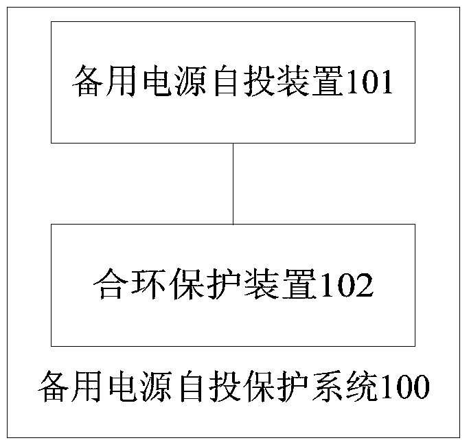
The invention discloses a backup power supply switchover protective system. The backup power supply switchover protective system comprises a backup power supply switchover device and a loop closing protective device, wherein the backup power supply switchover device is used for controlling a backup power supply to supply electricity when a main power supply malfunctions; the loop closing protective device is connected with the backup power supply switchover device and is used for protecting a backup power supply switchover loop when backup power supply switchover device performs switchover movement, wherein the backup power supply switchover loop comprises a backup power supply switchover device. According to the invention, the problem of flickering caused when the backup power supply switchover device resets automatically at low voltage in the prior art is solved.

Description

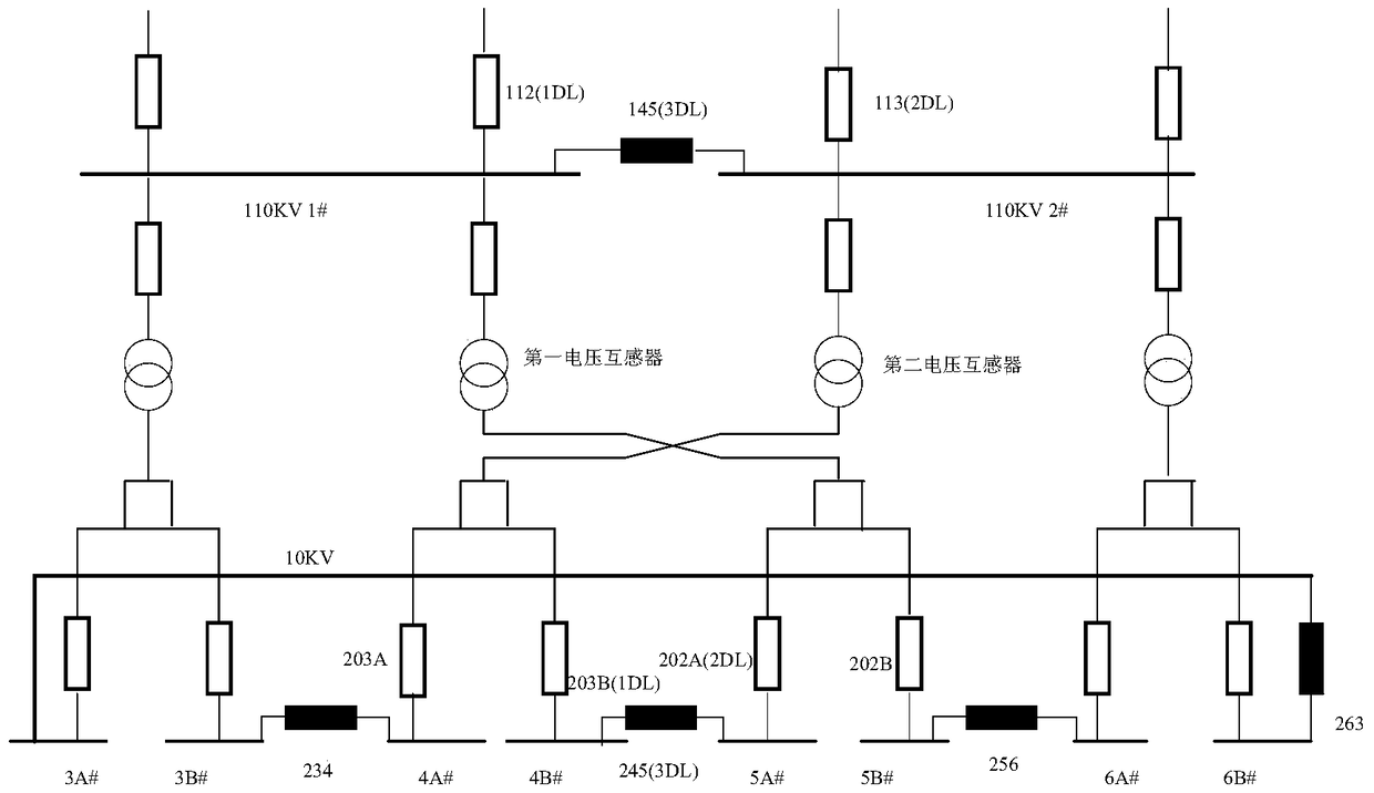
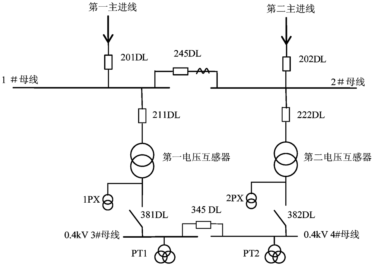
technical field [0001] The invention relates to the field of distribution networks, in particular to a backup power supply self-switching protection system. Background technique [0002] In the distribution network, the backup power self-injection devices mainly include 10kV and 0.4kV backup power self-injection devices. Under normal circumstances, the bus coupler in the backup power automatic switching device is in the sub-position, and the two sections of the bus are powered separately. When a certain power supply fails, the backup power supply self-switching device is put into the bus coupler, and the bus load of this section is taken out. In the maintenance process, in order to avoid short-term power outages for users, it is necessary to perform loop closing operation, that is, first close the contact and then disconnect the incoming line switch. The ring closing operation means that when the two incoming power sources are charged, the bus coupler is closed, and it is ...

Claims


Application Information

Patent Timeline
Patent Type & Authority Patents(China)
IPC IPC(8): H02H9/00
Inventor 吕立平谷君王立永竺懋渝袁清芳刘漫雨许冲冲王宁
Owner STATE GRID CORP OF CHINA
Learn More