Braking mechanism of baby carriage and baby carriage
A technology for a braking mechanism and a baby carriage, which is applied in the directions of baby carriage/stroller, multi-axle baby carriage/cradle, baby carriage/cradle accessories, etc., can solve the problems of large, laborious and inconvenient application, and achieve a simple structure. , Brake sensitive effect
- Summary
- Abstract
- Description
- Claims
- Application Information
AI Technical Summary
Problems solved by technology
Method used
Image
Examples
Embodiment 1
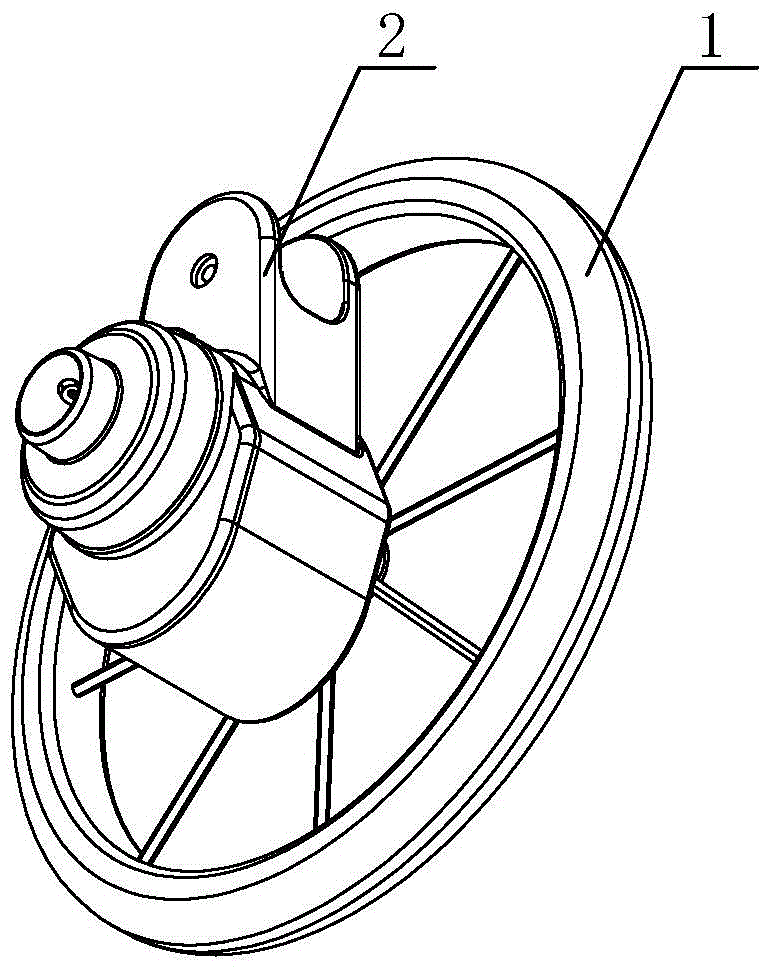
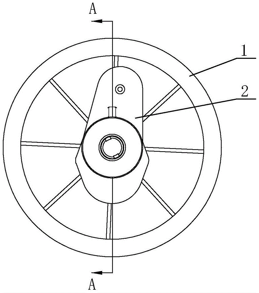
[0027] Such as Figure 1 to Figure 7 As shown, the brake mechanism of a baby carriage of the present invention can be used in the aforementioned baby carriage. The brake mechanism has a brake state and a brake release state. The brake mechanism includes a brake disc 5, a brake member 3 for braking the wheel 1, and an acceleration device 2. The brake member 3 is installed on the frame and brakes Piece 3 can move relative to the frame. The acceleration device 2 is a gear acceleration mechanism, and the acceleration device 2 has an input end and an output end. The acceleration device 2 includes a first gear shaft 6, a second gear shaft 7 and a transmission gear set 10. The first gear shaft 6 is installed at the input end of the acceleration device 2. The first gear shaft 6 is fixedly connected to the axle 4 of the wheel 1. The first gear shaft 6 rotates with the wheel 1, and the first gear shaft 6 has a first gear 8 . The second gear shaft 7 is installed at the output end of t...
Embodiment 2
[0033] Such as figure 1 , image 3 with Figure 8 As shown, the brake mechanism of the baby carriage of the second embodiment is based on the first embodiment, the structure of the brake 3 and the structure of the brake disc 5 are replaced and changed.
[0034] As mentioned above, the brake 3 is a bolt (not shown), the brake disc 5 is provided with a slot 12, the slot 12 is arranged along the radial direction of the brake disc 5, and one end of the slot 12 It extends to the outer edge of the brake disc 5 and forms an opening on the brake disc 5. There are multiple slots 12 and they are evenly distributed along the circumferential direction of the brake disc 5.
[0035] When the brake mechanism is in the braking state, the bolt is inserted into the slot 12 of the brake disc 5 to clamp the brake disc 5. When the brake mechanism is in the unbrake state, the bolt is separated from the slot 12 of the brake disc 5.
Embodiment 3
[0037] Similarly, in the third embodiment, the brake mechanism of the stroller is also based on the first embodiment by replacing the structure of the brake 3 and the structure of the brake disc 5.
[0038] As mentioned above, the brake 3 in the third embodiment is an elastic brake block (not shown in the figure). When the brake mechanism is in a braking state, the elastic brake block abuts on the brake disc 5 to clamp the brake disc 5 by friction. When the brake mechanism is in the unbrake state, the brake member 3 is separated from the brake disc 5.
[0039] The brake 3 is connected to a control device, and the control device controls the action of the brake 3. The control device may be an inductive controller, which realizes the operation of braking and releasing the brake by sensing the actions of the operator, and realizes automatic braking.
PUM
 Abstract
Description
Claims
Application Information
 - R&D Engineer
- R&D Manager
- IP Professional
- Industry Leading Data Capabilities
- Powerful AI technology
- Patent DNA Extraction
Browse by: Latest US Patents, China's latest patents, Technical Efficacy Thesaurus, Application Domain, Technology Topic, Popular Technical Reports.
© 2024 PatSnap. All rights reserved.Legal|Privacy policy|Modern Slavery Act Transparency Statement|Sitemap|About US| Contact US: help@patsnap.com


