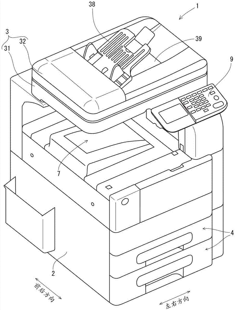
Image forming apparatus
An image and voltage technology, which is applied in the field of electrophotographic image forming devices, can solve the problems of low setting accuracy, low AC component setting accuracy, and setting charged voltage, etc., to achieve suppression of excessive discharge, suppression of damage, and prevention of Effect of inflow leakage current
- Summary
- Abstract
- Description
- Claims
- Application Information
AI Technical Summary
Problems solved by technology
Method used
Image
Examples
no. 1 approach >
[0164] Referring to the drawings, an image forming apparatus according to a first embodiment of the present invention will be described below. Image 6 It is a figure showing the structure of the table stored in the memory in the image forming apparatus of this embodiment. Figure 7 as well as Figure 8 It is a timing chart showing the transition timing of the measurement voltage in the current value measurement for calculating the discharge start voltage. Figure 9 It is a graph showing the relationship between the measurement voltage and the measurement current value for explaining the calculation method of the discharge start voltage.
[0165] Such as Image 6 As shown, the image forming apparatus 1 according to the present embodiment stores in the memory 111 a table that stores the measuring voltage Vpp corresponding to the environmental value (the temperature inside the device, the humidity inside the device, etc.) in the main body 2 of the device. fixed table (first s...
no. 2 approach >
[0185] Referring to the drawings, an image forming apparatus according to a second embodiment of the present invention will be described below. Figure 12 It is a figure showing the structure of the table stored in the memory in the image forming apparatus of this embodiment. In addition, in this embodiment, the same components and operations as those in the first embodiment are assigned the same reference numerals, and detailed descriptions thereof are omitted.
[0186] Such as Figure 12 As shown, and the first embodiment (refer to Image 6 ) similarly, the image forming apparatus 1 of this embodiment stores in the memory 111 a measurement voltage setting table (first setting table) DT1, a discharge start voltage correction table (first correction table) DT2, a measurement voltage correction table (second correction table) DT3 and measurement voltage setting table (second setting table) DT4, and further store charging voltage correction table (third correction table) DT5, ...
no. 3 approach >
[0199] Referring to the drawings, an image forming apparatus according to a third embodiment of the present invention will be described below. Figure 16 It is a figure showing the structure of the table stored in the memory in the image forming apparatus of this embodiment. In addition, in this embodiment, the same components and operations as those in the first embodiment are assigned the same reference numerals, and detailed descriptions thereof are omitted.
[0200] Such as Image 6 As shown, and the first embodiment (refer to Image 6 ) similarly, the image forming apparatus 1 of this embodiment stores in the memory 111 a measurement voltage setting table (first setting table) DT1, a discharge start voltage correction table (first correction table) DT2, a measurement voltage correction table (second calibration table) DT3 and measurement voltage setting table (second setting table) DT4, and further store a measurement voltage setting table (third setting table) DT6, whi...
PUM
 Abstract
Description
Claims
Application Information
 - R&D
- Intellectual Property
- Life Sciences
- Materials
- Tech Scout
- Unparalleled Data Quality
- Higher Quality Content
- 60% Fewer Hallucinations
Browse by: Latest US Patents, China's latest patents, Technical Efficacy Thesaurus, Application Domain, Technology Topic, Popular Technical Reports.
© 2025 PatSnap. All rights reserved.Legal|Privacy policy|Modern Slavery Act Transparency Statement|Sitemap|About US| Contact US: help@patsnap.com


