
Sensor and method for manufacturing a sensor

一种传感器、衬底的技术,应用在传感器领域,达到简化制造的效果

Active Publication Date: 2015-08-19
ROBERT BOSCH GMBH
View PDF4 Cites 4 Cited by
  • Summary
  • Abstract
  • Description
  • Claims
  • Application Information

AI Technical Summary

Problems solved by technology

In this case, decoupling of the detection element from mechanical stress can only be achieved with relatively high expenditure

Method used


Image

  • Sensor and method for manufacturing a sensor
  • Sensor and method for manufacturing a sensor
  • Sensor and method for manufacturing a sensor

Examples


Embodiment Construction

[0036] In the different figures, identical components are always provided with the same reference symbols and are therefore generally also described or illustrated only once in each case.

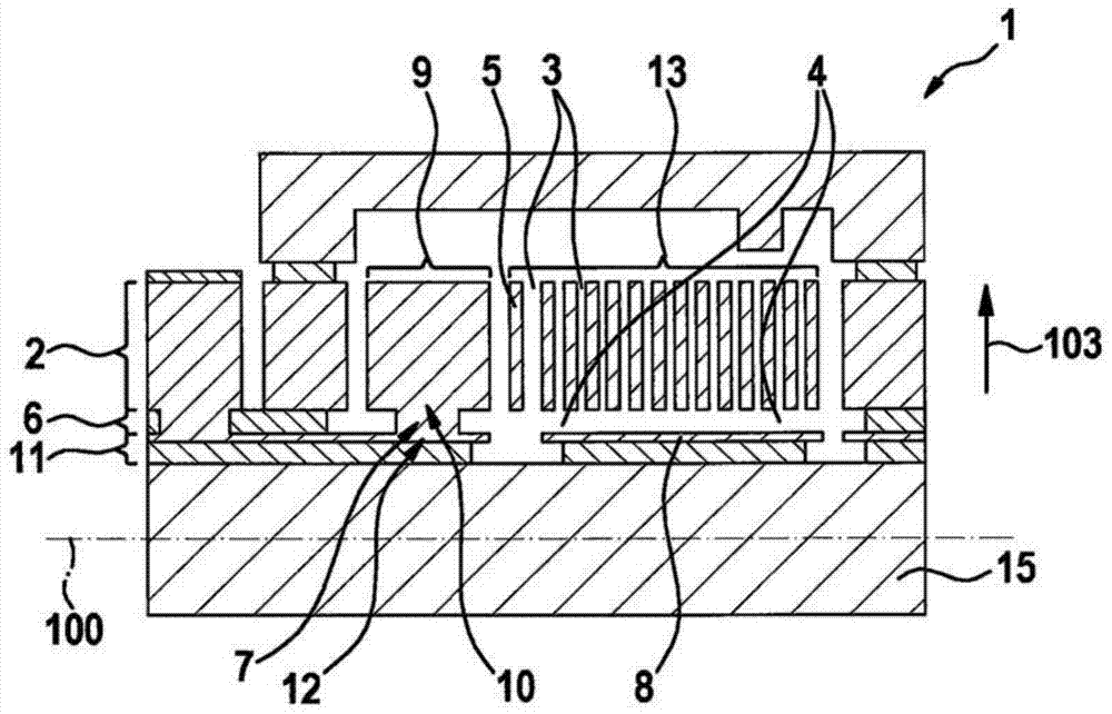
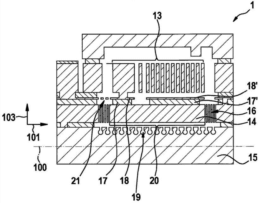
[0037] exist figure 1 A sensor 1 according to an embodiment of the invention, in particular an acceleration sensor and / or a rotational speed sensor, is shown in a sectional view, wherein the basic structure of the sensor 1 is mainly described here. Here, the basic structure comprises a microelectromechanical element (MEMS element) 1' movable relative to the substrate 15 of the sensor 1 and a fixed structure 9 to which the MEMS element 1' is spring-elastically coupled. An offset or offset movement of the movable element 1' can be detected by the sensor 1 as a function of the capacitance change.

[0038] A movable MEMS element 1' is produced by means of an etching method from a (relatively thick) epitaxially (on the substrate 15 of the sensor 1 ) deposited polysilicon layer 2 (epitaxial pol...


PUM


Abstract

A sensor includes: a substrate, a microelectromechanical structure, and a decoupling structure. The decoupling structure is anchored on the substrate, and the microelectromechanical structure is anchored on the decoupling structure. The microelectromechanical structure and the decoupling structure are movable in relation to the substrate. The decoupling structure is situated between the microelectromechanical structure and the substrate.

Description

technical field [0001] The invention relates to a sensor according to the preamble of claim 1 . Background technique [0002] Such sensors are generally known. For example, acceleration sensors and rotational speed sensors are known which have a substrate and a detection element which is movable relative to the substrate. In known sensors, the detection element is relatively strongly influenced by the mechanical stress of the substrate. In this case, decoupling of the detection element from mechanical stress can only be achieved with relatively high complexity. Contents of the invention [0003] It is an object of the present invention to provide a sensor and a method for producing a sensor in which, compared to the prior art, an improved decoupling of the detection element from mechanical stress is achieved and, moreover, the production of the sensor is simplified. [0004] Compared with the prior art, the sensor according to the invention according to the side claims ...

Claims


Application Information

Patent Timeline
Patent Type & Authority Applications(China)
IPC IPC(8): B81B7/00B81C1/00
CPCB81B7/0016B81B2201/0242B81B5/00B81B3/0048B81B7/0048B81C1/0019B81B2201/0235B81B7/0006B81C1/00198B81C1/0015B81C1/00325B81C1/00666B81B3/0054
Inventor J·赖因穆特
Owner ROBERT BOSCH GMBH
Learn More