
A rotor unmanned aerial vehicle system and navigation method for automatic inspection of bridges and tunnels

A four-rotor drone and automatic inspection technology, applied in the field of rotor drones, can solve problems such as large depth, complex environment, and high quality requirements for operators

Active Publication Date: 2017-04-19
恒华数元科技(天津)有限公司
View PDF4 Cites 0 Cited by
  • Summary
  • Abstract
  • Description
  • Claims
  • Application Information

AI Technical Summary

Problems solved by technology

[0004] At present, the navigation of rotor UAVs mainly relies on GPS and manual control. Although this method can alleviate the difficulties of bridge and tunnel inspection tasks at this stage to a certain extent, GPS signals in areas such as bridges and tunnels are often blocked and rely on GPS for work. The device can not play its role, resulting in the rotor UAV can not locate the position of the body or even an accident
In addition, the control of the rotor UAV requires manual remote control, and the operator needs to be able to operate the rotor UAV proficiently and has completed various inspection tasks, which requires a high quality of the operator
At the same time, the environment in the bridge and tunnel area is relatively complex and the depth is relatively large. The remote control signal of the rotor drone is easily interfered or even shielded. Once the remote controlled rotor drone loses the control signal, it is likely to cause a serious accident

Method used


Image

  • A rotor unmanned aerial vehicle system and navigation method for automatic inspection of bridges and tunnels
  • A rotor unmanned aerial vehicle system and navigation method for automatic inspection of bridges and tunnels
  • A rotor unmanned aerial vehicle system and navigation method for automatic inspection of bridges and tunnels

Examples


Embodiment

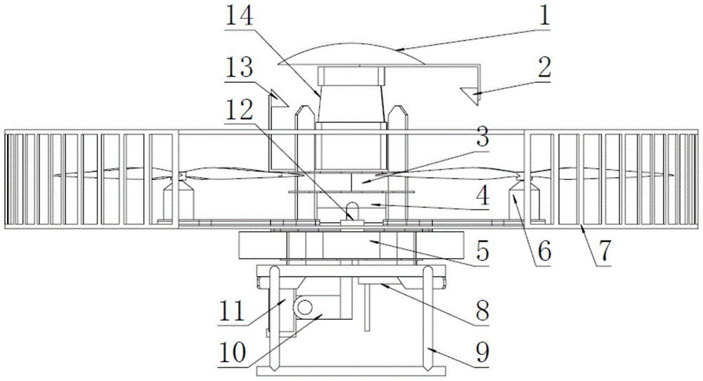
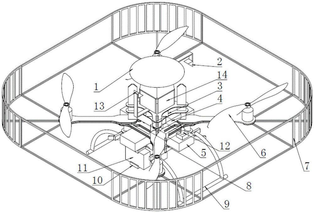
[0026] One, at first introduce the concrete structure and navigation method of the device involved in the present invention, the present invention mainly comprises:

[0027] The first part, the design of the body of the automatic inspection rotor UAV:

[0028] Due to the limitations of production technology and materials, most of the current rotor drones have shortcomings such as small payload and short flight duration. Therefore, the volume and weight of various sensors must be fully considered when designing the body of the rotor drone. , power consumption and other issues, while minimizing the amount of sensors. Based on this, when the present invention designs the body of the rotor UAV, a UTM-30LX two-dimensional laser radar, a GPS module, an IMU module, a miniature high-definition camera and two right-angle reflective prisms are loaded on the body as the rotor unmanned aerial vehicle. The sensor of the machine, an RC module, a high-definition video transmission, and a co...


PUM


Abstract

The invention provides an unmanned-gyroplane system used for automatic inspection of bridges and tunnels and a navigation method, belonging to the field of automatic detection of bridge and tunnel diseases. According to the invention, aimed at the characteristics of bridge and tunnel areas, the unmanned gyroplane inspection system which realizes autonomous navigation in virtue of GPS, laser radar and IMU is designed; and the system realizes autonomous inspection of an open bridge area by using a GPS navigation system and autonomous inspection of a closed tunnel area by using a laser radar navigation system, dodging of bridges, tunnels and motor vehicles via an automatic evadible system, and shooting of images of key areas, wherein the images are sent back to a ground station, and thematic pictures of diseases of bridge and tunnels are generated by the ground station and provided to related personnel for use. The unmanned-gyroplane system provided by the invention has the characteristics of mobility and flexibility in the process of inspection and has the advantages of a wide inspection coverage area, unblocking of traffic, real-time returning of live shots, etc.

Description

technical field [0001] The invention relates to a rotary-wing unmanned aerial vehicle for automatic inspection in areas such as bridges and tunnels. It utilizes GPS and two-dimensional laser radar to realize the autonomous flight control of the rotary-wing unmanned aerial vehicle in areas such as bridges and tunnels where GPS signals are easily lost, and then completes automatic inspection. The inspection operation specifically relates to a rotor unmanned aerial vehicle system and a navigation method for automatic inspection of bridges and tunnels. Background technique [0002] my country is a mountainous country. In order to improve the economic speed of road and railway transportation, road construction in mountainous areas usually takes the form of bridges and tunnels. As of the end of 2013, my country had more than 730,000 bridges and tunnels, ranking first in the world in total length. my country has also become the country with the most tunnels and underground projects...

Claims


Application Information

Patent Timeline
Patent Type & Authority Patents(China)
IPC IPC(8): B64C27/08G01S19/49G01C21/16
Inventor 陈显龙陈晓龙许贤泽刘盼盼徐逢秋贺志刚
Owner 恒华数元科技(天津)有限公司
Learn More