A U-shaped vibration isolation device with a composite material structure

A composite material and vibration isolation technology, which is applied in the direction of propulsion engine, transportation and packaging, ship construction, etc., to achieve the effects of locking, reducing underwater noise, and improving low-frequency vibration isolation performance

Active Publication Date: 2017-03-08
中国船舶重工集团公司第七〇二研究所
View PDF7 Cites 2 Cited by
  • Summary
  • Abstract
  • Description
  • Claims
  • Application Information

AI Technical Summary

Problems solved by technology

[0002] At present, in the vibration isolation application of traditional power mechanical equipment, such as the vibration isolation of the propulsion motor, it is generally installed directly on the hull base through the vibration isolator. Since the hull base is located directly below the propulsion motor, the propulsion motor Part of the periodic vibration generated during rotation is isolated by the vibration isolator, and a considerable part is directly transmitted to the hull structure through the hull base, which excites the hull structure to vibrate and causes underwater radiated noise. In order to reduce the above-mentioned structural vibration and Noise radiation, the installation of power mechanical equipment is usually installed by means of intermediate installation components, that is, the vibration isolation device is installed on the hull base. The matching relationship of the installation base of mechanical equipment directly affects the performance of the vibration isolation system. At the same time, the design idea of ​​vibration reduction and isolation of power mechanical equipment presents a contradictory relationship with the high neutrality requirements of power mechanical equipment. It is generally required to adopt flexible design ideas in the design of equipment vibration reduction and vibration isolation, but in actual engineering, other equipment or structures connected to power machinery are not allowed to have large deformations, such as propulsion motor shafts, gearbox tail shafts, etc. Therefore, it is not suitable to adopt an overly flexible design, which becomes a technical bottleneck restricting the vibration reduction and vibration isolation design of such equipment. In addition, the traditional vibration isolation idea also encounters a technical bottleneck in reducing the low-frequency strong line spectrum noise of power machinery equipment. Therefore, it is urgent to design a vibration isolation device

Method used


Image

  • A U-shaped vibration isolation device with a composite material structure
  • A U-shaped vibration isolation device with a composite material structure
  • A U-shaped vibration isolation device with a composite material structure

Examples


Embodiment Construction

[0021] The specific embodiments of the present invention will be described below with reference to the accompanying drawings.

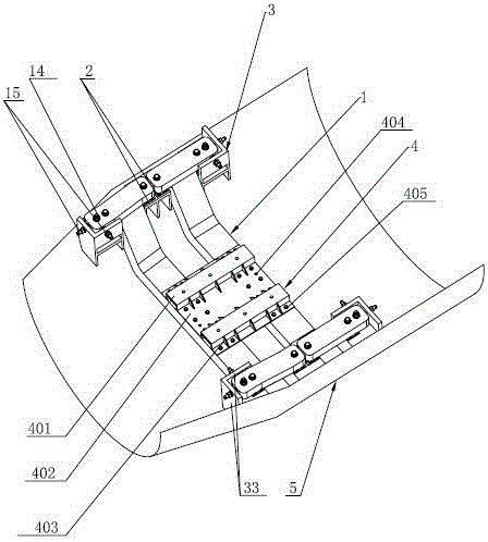
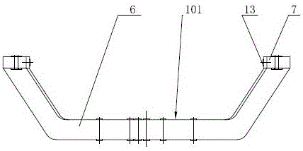
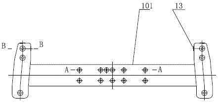
[0022] like figure 1 As shown, a U-shaped vibration isolation device with a composite material structure includes an equipment mounting base 4, the equipment mounting base 4 is fixedly connected with a sandwich composite vibration isolation raft 1, and the sandwich composite vibration isolation raft 1 is at least composed of It is composed of two sandwich composite material structural beams 101 arranged at intervals. In the present invention, there are two sandwich composite material structural beams 101, which are located inside and outside of each sandwich composite material structural beam 101, and are located at the inner and outer sides of each sandwich composite material structural beam 101. The end is connected to the boat hull steel base 3 through the vibration isolator 2. The boat hull steel base 3 is composed of the first layer panel 31, the...


PUM


Abstract

The invention relates to a U-type vibration isolating device with a novel composite material structure. The U-type vibration isolating device comprises an equipment installing base, wherein the equipment installing base is fixedly connected with a vibration isolating raft frame of a sandwich composite material; the sandwich composite material is at least composed of two sandwich composite material structural beams arranged at intervals; inside and outside of every sandwich composite material structural beam and the end part of the sandwich composite material structural beam are connected with a hull steel substrate through a vibration isolator; three-directional limiting mechanisms are further arranged at the outside and the end part of every sandwich composite material structural beam; the three-directional limiting mechanisms are respectively and fixedly connected with the hull steel substrate and the sandwich composite material structural beams. The U-type vibration isolating device combines the vibration isolating raft frame, the vibration isolator and the three-directional limiting mechanisms; obviously damping effect is generated within a wide frequency band scale, and underwater noise caused by transmitting vibration of a power mechanical device to a hull structure is reduced.

Description

technical field [0001] The invention relates to the field of vibration isolation, in particular to a U-shaped vibration isolation device with a composite material structure for marine power machinery and marine equipment. Background technique [0002] At present, in the vibration isolation application of traditional power machinery equipment, such as the vibration isolation of the propulsion motor, it is generally installed directly on the hull base through the vibration isolator. Since the hull base is located directly under the propulsion motor, the propulsion motor is A part of the periodic vibration generated during rotation is isolated by the vibration isolator, and the other considerable part is directly transmitted to the hull structure through the hull base, which stimulates the hull structure to vibrate and causes underwater radiated noise. Noise radiation, the installation of power machinery equipment is generally installed on the base of the hull by means of inter...

Claims


Application Information

Patent Timeline
Patent Type & Authority Patents(China)
IPC IPC(8): B63H21/30
Inventor 李永胜王纬波顾笑冬刘忠族吴有生吴健严斌李泓运
Owner 中国船舶重工集团公司第七〇二研究所
Why Eureka
Try Eureka