Eureka AIR delivers breakthrough ideas for toughest innovation challenges, trusted by R&D personnel around the world.

Prefabricated component production table form, production method and production line including the production table formwork

A technology of prefabricated components and table molds, which is applied in the direction of manufacturing tools, ceramic molding machines, etc., can solve the problem of site constraints and cannot produce multiple prefabricated components at the same time.

Active Publication Date: 2017-07-07
筑友智造智能科技有限公司
View PDF6 Cites 0 Cited by
  • Summary
  • Abstract
  • Description
  • Claims
  • Application Information

AI Technical Summary

Problems solved by technology

[0005] Based on this, it is necessary to solve the problem that the production of prefabricated components by fixed table formwork is easily limited by the site and cannot produce multiple prefabricated components at the same time, and provide a prefabricated component production table mold, production method and production method that can produce multiple prefabricated components at the same time. The production line that contains the table formwork

Method used


Image

  • Prefabricated component production table form, production method and production line including the production table formwork
  • Prefabricated component production table form, production method and production line including the production table formwork
  • Prefabricated component production table form, production method and production line including the production table formwork

Examples


Embodiment Construction

[0034] In order to facilitate the understanding of the present invention, the present invention will be described more fully below with reference to the associated drawings. Preferred embodiments of the invention are shown in the accompanying drawings. However, the present invention can be embodied in many different forms and is not limited to the embodiments described herein. On the contrary, these embodiments are provided to make the understanding of the disclosure of the present invention more thorough and comprehensive.

[0035] It should be noted that when an element is referred to as being “fixed” to another element, it can be directly on the other element or there can also be an intervening element. When an element is referred to as being "connected to" another element, it can be directly connected to the other element or intervening elements may also be present.

[0036] Unless otherwise defined, all technical and scientific terms used herein have the same meaning as...


PUM


Abstract

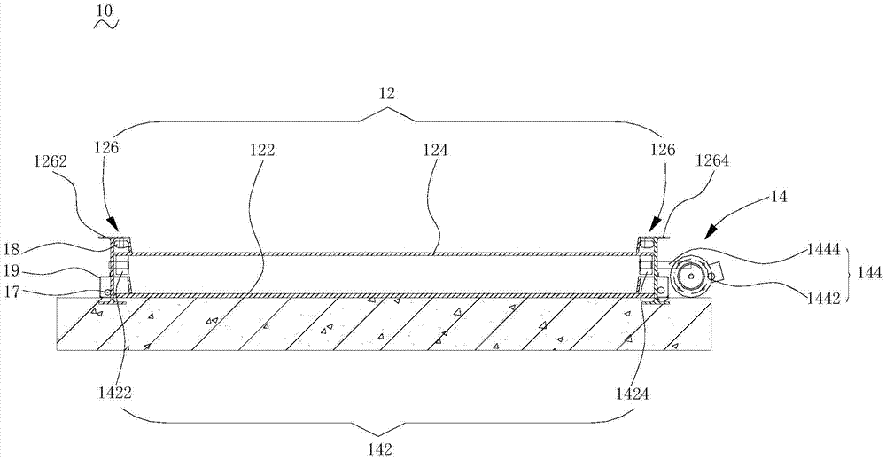
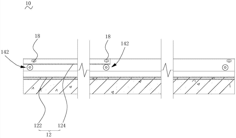
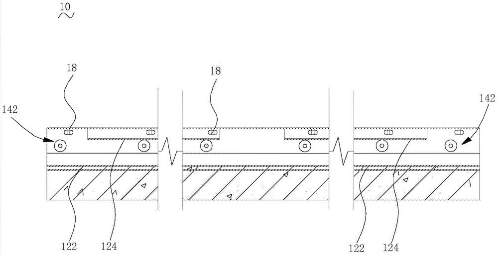
The invention discloses a prefabricated part production bench formwork and a production line including the production bench formwork. The prefabricated part production bench formwork comprises bench formwork units and driving units. Each bench formwork unit comprises a bottom bench formwork layer, at least one upper bench formwork layer and a support, the bottom bench formwork layer is arranged at the bottom of the support, the upper bench formwork layer is movable relative to the length direction of the support and is located on the bottom bench formwork layer. Each driving unit comprises a driving wheel set and a power assembly, wherein the driving wheel set is rotationally connected to the corresponding support, the corresponding upper bench formwork layer is arranged on the driving wheel set, and the power assembly is installed on the corresponding support and is in transmission connection with the driving wheel set. The prefabricated part production bench formwork is adopted, the driving wheel sets are driven by the power assemblies and drive the upper bench formwork layer to move in the length direction of the supports, multiple prefabricated parts can be poured on the same site, the production efficiency is improved, and the building cost is reduced. The invention further provides a prefabricated part production method.

Description

technical field [0001] The invention relates to the technical field of concrete prefabricated component production, in particular to a prefabricated component production table form, a production method and a production line including the production table form. Background technique [0002] Prefabricated concrete components are building components prefabricated in factories with concrete as the basic material, including beams, slabs, columns and building repair parts, etc., which provide great convenience for reducing construction costs and shortening the construction period. Therefore, it has been Widely used in building construction. [0003] Generally, in the production of concrete prefabricated components, the concrete is poured into the fixed table formwork through the distribution machine, and the vibrating table drives the table formwork to vibrate. The concrete in the table formwork fills the gaps in the table formwork under the action of vibration, and then the prefa...

Claims


Application Information

Patent Timeline
Patent Type & Authority Patents(China)
IPC IPC(8): B28B23/00
CPCB28B23/00
Inventor 彭海辉
Owner 筑友智造智能科技有限公司
Why Eureka
Eureka Blog
Learn More