Clamping device, locking nut, locking component, welding gun with same and fastening method

A technology for locking nuts and clamps, which is applied in the direction of threaded fasteners, nuts, connecting components, etc., which can solve the problems of cumbersome installation and disassembly of clamps, cumbersome installation and disassembly of clamps, etc., and achieve convenient installation and installation and the effect of easy disassembly

Active Publication Date: 2015-08-19
BEIJING BORGWARD AUTOMOBILE CO LTD
View PDF5 Cites 0 Cited by
  • Summary
  • Abstract
  • Description
  • Claims
  • Application Information

AI Technical Summary

Problems solved by technology

[0005] Therefore, the first technical problem to be solved by the present invention is to overcome the cumbersome technical problems of clamp installation and disassembly in the prior art, so as to provide a clamp that is easy to install and disassemble.
[0006] The second technical problem to be solved by the present invention is to overcome the cumbersome technical problem of clamp installation and disassembly in the prior art, so as to provide a lock nut that is used for the clamp and facilitates the installation and disassembly of the clamp
[0007] The third technical problem to be solved by the present invention is to overcome the cumbersome technical problems of the installation and disassembly of the clamp in the process of forming the locking assembly in the prior art, so as to provide a locking assembly that facilitates the installation and disassembly of the clamp

Method used


Image

  • Clamping device, locking nut, locking component, welding gun with same and fastening method
  • Clamping device, locking nut, locking component, welding gun with same and fastening method
  • Clamping device, locking nut, locking component, welding gun with same and fastening method

Examples


Embodiment 1

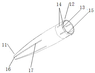
[0052] Such as figure 2 , image 3 As shown, this embodiment provides a clamp, which includes a hollow clamp body 1, the clamp body 1 has a clamping part 11, and the clamping part 11 has a clamping opening for clamping foreign objects 16. The cross-sectional area of ​​the locking part 11 gradually decreases along the direction from its root to the clamping opening 16, and the locking part 11 is formed with several grooves 17 along its axial direction, and the grooves 17 are in line with the clamping opening 16. The clamping port 16 is connected, and the groove 17 provides convenience for the deformation of the clamping port 16, so that the clamping port 16 can clamp objects of different sizes.

[0053] The clamp of this embodiment also includes a mounting part 12 fixedly connected with the clamping part 11, the clamping part 11 and the mounting part 12 are integrally formed, and the minimum cross-sectional area of ​​the mounting part 12 is The size is not smaller than the m...

Embodiment 2

[0063] Such as Figure 4 , Figure 5 As shown, this embodiment provides a lock nut, the lock nut is used for locking with the clamp described in Embodiment 1, and includes a hollow nut body 2, and the nut body 2 has a The locking body 13 of the locking device is inserted into several insertion parts 21, and the matching locking part 22 that is arranged between adjacent insertion parts 21 and is connected with the insertion part 21 through a transition part 23, and the matching locking part 22 is used for When the locking body 13 located in the insertion portion 21 is rotated at a certain angle and slides into the mating locking portion 22 through the transition portion 23, the locking surface 15 of the locking body 13 is relative to the insertion portion. 21 provides a greater locking force to cooperate with the locking body 13 to lock.

[0064]When the lock nut of this embodiment is used for locking fit with the lock nut in Example 1, the locking surface 15 of the clamp is ...

Embodiment 3

[0070] Such as Figure 6 As shown, this embodiment provides a locking assembly, including a hollow lock nut and the hollow clamp located inside the lock nut, the clamp has a clamping portion 11 for clamping foreign objects And the installation part 12 fixedly connected with the clamping part 11, the installation part 12 has a structure that enables itself to be elastically deformed at least along the circumferential direction and the radial direction, and the installation part 12 is provided with several folds along the outer circumference. To the locking body 13 of the clamping part 11, the locking body 13 has a locking surface 15; the locking nut has several insertion parts 21 for inserting the locking body 13 of the clamp, and is arranged on The mating locking portion 22 between adjacent insertion portions 21 and connected to the insertion portion 21 through the transition portion 23, the locking body 13 located in the insertion portion 21 is rotated at a certain angle and ...


PUM


Abstract

The invention discloses a clamping device and a locking nut used for locking the clamping device. The clamping device and the locking nut have corresponding specific technical characteristics that particularly, an installing portion of the clamping device can deform at least in the circumferential direction and the radial direction, a plurality of locking bodies are arranged on the installing portion along the external circumference, and each locking body is provided with a locking face locked with a cooperation locking portion under the function of external locking force; the locking nut is provided with an inserting portion and a cooperation locking portion connected with the inserting portion through a transition portion. When the clamping device and the locking nut are matched to perform locking, the locking faces of the clamping device are aligned with the inserting portion of the locking nut to be inserted into the locking nut, the clamping device is rotated, in addition, the locking faces of the locking bodies are rotated to the cooperation locking portion of the locking nut from the inserting portion of the locking nut, in the process, the locking force born by the locking faces is increased, and the installation of the clamping device is very convenient.

Description

technical field [0001] The invention relates to a clamp for a nail clamp, a lock nut, a lock assembly, a welding gun with the same and a fastening method, and belongs to the technical field of component clamping. Background technique [0002] The clamp is used to clamp the clamped object, so as to perform other operations on the clamped object. At present, the clamp has been widely used in the field of pre-industrial production and post-processing technology. Among them, the representative of the clamp is the nail clamp. [0003] The nail clamp in the prior art has a clamping part, the clamping part has a clamping opening, and a groove for changing the size of the clamping opening and providing elastic deformation force for the clamping part, and also includes a The mounting part of the tight part is integrally formed, and a flange is formed on the outer wall of the mounting part along the circumferential direction. This type of nail clamp is mainly used in the front struc...

Claims


Application Information

Patent Timeline
Patent Type & Authority Applications(China)
IPC IPC(8): B23K9/32B23K9/20F16B37/00
Inventor 王文标
Owner BEIJING BORGWARD AUTOMOBILE CO LTD
Why Eureka
Try Eureka