


Quick Research
Generate reliable direction feasibility study reports for your R&D in just a few steps.

Technical Q&A
Discover and master advanced knowledge NOW. Basics, ideas, possibilities, all at once.

Find Solutions
As an expert in R&D theories, this can generate solutions to your technical problems instantly.

Evaluate Feasibility
Analyze your overall solution with one click, know your potential R&D risks in advance.

Monitor Landscape
Get weekly tech updates, stay abreast of the latest tech innovations and key insights.
Medical marking device for positioning
A marking and device technology, applied in the field of medical devices, can solve problems such as being difficult to move, achieve good deformation recovery ability, and facilitate surgical removal of lesions.
- Summary
- Abstract
- Description
- Claims
- Application Information
AI Technical Summary
Problems solved by technology
Method used
Image

Examples
Embodiment 1
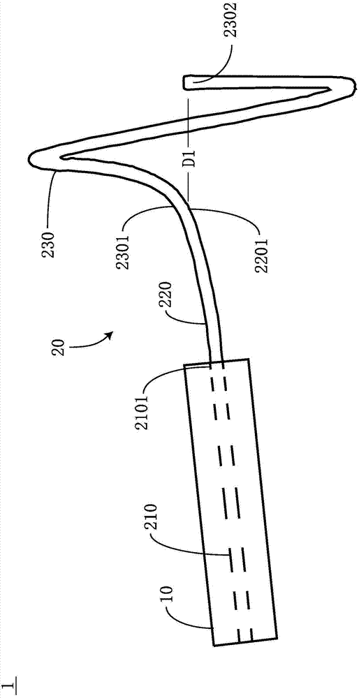
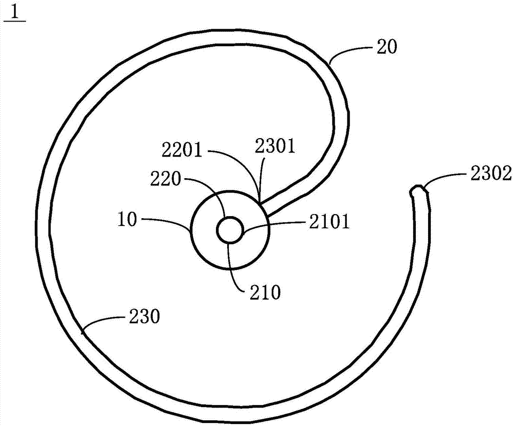
[0032] like figure 1 as well as figure 2 As shown, it is a schematic diagram of the marking structure and an end projection view of the first embodiment of the present invention. The medical marking device 1 disclosed in the embodiment of the present invention includes a marking body 10 and a first anchoring structure 20 . The first anchoring structure 20 includes a fixing section 210 , a first extending section 220 and a first helical section 230 .
[0033] Here, the shape of the marking body 10 can be a hollow cylinder, but it is also conceivable that it can also be in other shapes, such as a sphere, an ellipsoid, a cuboid with relatively gentle edges and corners, etc. The reason why these shapes are selected is to avoid When it is implanted into the human body, too sharp edges and corners will bring discomfort to the human body and even stimulate the organs of the human body. That is to say, there are not too many restrictions on its specific shape. It should be pointed o...
Embodiment 2
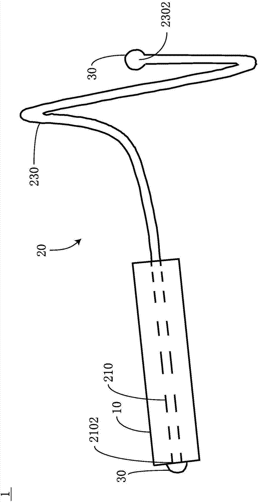
[0042] like image 3 As shown, it is a schematic diagram of the marking structure of the second embodiment of the present invention. This embodiment is based on the first embodiment. Please refer to image 3 , the medical marking device 1 disclosed in the embodiment of the present invention also includes two end balls 30, and the two end balls 30 are respectively arranged on the terminal end 2302 of the first helical section 230 and the second end of the fixed section 210. end 2102 , and the diameter of the end sphere 30 is larger than the diameters of the fixing section 210 and the first helical section 230 . Furthermore, the end ball 30 disposed at the second end 2102 of the fixing section 210 clamps and fixes the first anchoring structure 20 in the marker body 10 .
[0043] Specifically, the two end spheres 30 are respectively arranged at the two ends of the first anchoring structure 20, and their diameters are larger than the diameter of the superelastic material of the f...
Embodiment 3
[0047] like Figure 4 As shown, it is a schematic diagram of the marking structure of the third embodiment of the present invention. This embodiment is based on the first embodiment. The medical marking device 1 disclosed in the embodiment of the present invention also includes a second anchoring structure 40. The second anchoring structure 40 includes a second extension section 410 and a second helical section 420 . The second extension section 410 is disposed on the second end 2102 of the fixing section 210 and extends in a direction relative to the first extension section 220; The first end 4101 of the second extension section 410, the terminal end 4202 of the second helical section 420 is located in the extension direction of the second extension section 410 and is separated from the first end 4101 of the second extension section 410 by a distance D2 ; Wherein, the helical direction of the second helical segment 420 is opposite to the helical direction of the first helica...
PUM
 Abstract
Description
Claims
Application Information
 - R&D Engineer
- R&D Manager
- IP Professional
- Industry Leading Data Capabilities
- Powerful AI technology
- Patent DNA Extraction
Browse by: Latest US Patents, China's latest patents, Technical Efficacy Thesaurus, Application Domain, Technology Topic, Popular Technical Reports.
© 2024 PatSnap. All rights reserved.Legal|Privacy policy|Modern Slavery Act Transparency Statement|Sitemap|About US| Contact US: help@patsnap.com