A magnetic biofilter

A biological filter and anoxic biological filter technology, applied in the field of new magnetic biological filter, can solve the problems such as the new magnetic filter has not appeared, the lack of nutrient growth of organisms is not good, the filter is blocked and the frequency of backwashing, etc., to achieve adhesion Good performance, improve microbial utilization, and enhance the effect of removal performance

Active Publication Date: 2017-01-18
云南傲远市政建设工程有限公司
View PDF4 Cites 0 Cited by
  • Summary
  • Abstract
  • Description
  • Claims
  • Application Information

AI Technical Summary

Problems solved by technology

[0010] Although BAF and AF have the above-mentioned many advantages, but both BAF and AF exist in different degrees that the bottom of the filter tank is easy to be blocked and difficult to clean, and the amount of biofilm on the biological carrier packing at different heights in BAF and AF is quite different. The uniformity of biomass is poor, often showing that the front end (or lower end) of the biological filler in the filter grows better and has a larger biomass, while the rear end (or upper end) grows poorly or even does not grow due to lack of nutrients, and the biomass is less , which can also easily cause blockage of the filter, resulting in excessive backwash frequency, large power consumption, and affecting the stable operation of the filter
In view of the above-mentioned shortcomings of the biological filter, corresponding research has been done at home and abroad, but most of them focus on the backwashing method of the filter and the filter packing that can present a fluidized state, and this new type of magnetic filter with many advantages pool never appeared

Method used


Image

  • A magnetic biofilter
  • A magnetic biofilter
  • A magnetic biofilter

Examples


Embodiment 1

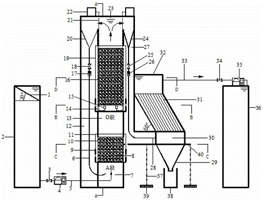
[0033] Embodiment 1: as Figure 1-7 As shown, a new type of magnetic biofilter includes a water inlet grid 1, a water inlet tank 2, a valve in front of the pump 3, a water inlet pump 4, a water inlet pipe 5, the main part of the integrated equipment, an outlet pipe 33 after sedimentation, and a water outlet pipe 33 after sedimentation. Water outlet valve 34, outlet water disinfection device 35, outlet water collection tank 36, the main part of the integrated equipment is composed of the main part of the bioreactor, the accessory part of the bioreactor, and the sedimentation part. The main part of the bioreactor and the sedimentation part pass through the main part of the integrated equipment The plexiglass walls on the right are welded tightly together,

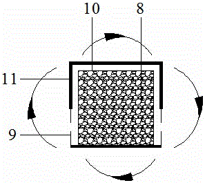
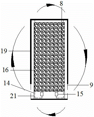
[0034] The main part of the bioreactor consists of a water flow mixing zone 7, a section A anoxic biological filter 10, a return pipe tank 12, an ascending water buffer zone 13, an O section aerobic aerated biological filter ...

Embodiment 2

[0040] Embodiment 2: as Figure 1-7 As shown, a new type of magnetic biofilter includes a water inlet grid 1, a water inlet tank 2, a valve in front of the pump 3, a water inlet pump 4, a water inlet pipe 5, the main part of the integrated equipment, an outlet pipe 33 after sedimentation, and a water outlet pipe 33 after sedimentation. Water outlet valve 34, outlet water disinfection device 35, outlet water collection tank 36, the main part of the integrated equipment is composed of the main part of the bioreactor, the accessory part of the bioreactor, and the sedimentation part. The main part of the bioreactor and the sedimentation part pass through the main part of the integrated equipment The plexiglass walls on the right are welded tightly together,

[0041]The main part of the bioreactor consists of a water flow mixing zone 7, a section A anoxic biological filter 10, a return pipe tank 12, an ascending water buffer zone 13, an O section aerobic aerated biological filter 1...

Embodiment 3

[0049] Embodiment 3: as Figure 1-7 As shown, a new type of magnetic biofilter includes a water inlet grid 1, a water inlet tank 2, a valve in front of the pump 3, a water inlet pump 4, a water inlet pipe 5, the main part of the integrated equipment, an outlet pipe 33 after sedimentation, and a water outlet pipe 33 after sedimentation. Water outlet valve 34, outlet water disinfection device 35, outlet water collection tank 36, the main part of the integrated equipment is composed of the main part of the bioreactor, the accessory part of the bioreactor, and the sedimentation part. The main part of the bioreactor and the sedimentation part pass through the main part of the integrated equipment The plexiglass walls on the right are welded tightly together,

[0050] The main part of the bioreactor consists of a water flow mixing zone 7, a section A anoxic biological filter 10, a return pipe tank 12, an ascending water buffer zone 13, an O section aerobic aerated biological filter ...


PUM


Abstract

The present invention relates to a novel magnetic biological filtration pool, and belongs to the technical field of environmental protection and water treatment equipment. The novel magnetic biological filtration pool comprises a water inlet grid, a water inlet box, a fore-pump valve, a water inlet pump, a water inlet pipe, an integrated equipment main body part, an after-precipitation water outlet pipe, an after-precipitation water outlet valve, an effluent disinfection device, and an effluent collection pool, wherein the integrated equipment main body part comprises a bioreactor main body portion, a bioreactor attachment portion and a precipitation portion, and the bioreactor main body portion and the precipitation portion are closely and integrally welded and connected through the organic glass wall on the right side of the integrated equipment main body part. According to the present invention, the impurity on the magnetic filler can easily loosen and shed, the back washing is not required, and the filtration pool clogging can be effectively prevented; and the condition of the water flow in the magnetic adsorption filler in the filtration pool and the uniformity of the organism on the filler can be improved, such that the problem of the non-uniform growth of the biological films on the filler front end and the filler rear end in the traditional filtration pool is avoided so as to substantially increase the microorganism utilization rate of the filtration pool filler.

Description

technical field [0001] The invention relates to a novel magnetic biological filter, which belongs to the technical fields of environmental protection and water treatment equipment. Background technique [0002] The overall trend of the development of modern sewage treatment technology and equipment is to compress and simplify the process as much as possible under the premise of ensuring the quality of effluent water, to save energy and reduce consumption, and to operate greenly. The biological filter (Biological Filter, BF) process is short, occupies less land, operates economically and has good treatment effect, which is in line with the development trend of modern sewage treatment technology and equipment. be widely promoted. [0003] BF is a process of sewage biofilm treatment, that is, filling a certain amount of filler with a high specific surface area in the reactor to facilitate the growth of microorganisms. Under suitable conditions, a large number of microorganisms...

Claims


Application Information

Patent Timeline
Patent Type & Authority Patents(China)
IPC IPC(8): C02F9/14
Inventor 关清卿朱友利施永生李驰昊施宇震
Owner 云南傲远市政建设工程有限公司
Why Eureka
Try Eureka