Multiple-piece tail wing structure

A multi-piece, rear wing technology, applied in the direction of aerodynamic improvement, body, road transportation emission reduction, etc., can solve the problems of slippage, vehicle breakthrough, difficult to alleviate, etc., to suppress body roll, improve acceleration and top speed performance , The effect of improving cornering speed and driving stability

Inactive Publication Date: 2015-08-12
ZHEJIANG SCI-TECH UNIV
View PDF8 Cites 6 Cited by
  • Summary
  • Abstract
  • Description
  • Claims
  • Application Information

AI Technical Summary

Problems solved by technology

[0003] In the actual driving process, especially in the case of high-speed curves, the car will have a tendency to roll to the outside of the curve due to the centrifugal effect, and the positive pressure on the tires located on the inside of the curve is reduced, while the tires on the outside of the curve The positive pressure on the tires increases, and the car has a large roll, which will easily cause the car to break through the adhesion limit of the outer wheel of the curve and slip.
However, since the front and rear wings exert the same downforce on the left and right sides of the car, it is still difficult to alleviate this situation

Method used


Image

  • Multiple-piece tail wing structure
  • Multiple-piece tail wing structure
  • Multiple-piece tail wing structure

Examples


Embodiment Construction

[0025] The present invention will be further described below in conjunction with the accompanying drawings and specific embodiments.

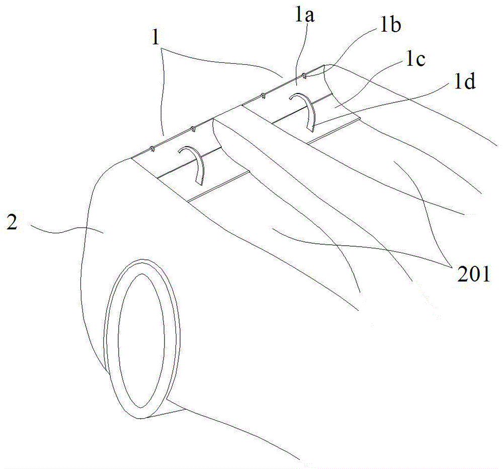
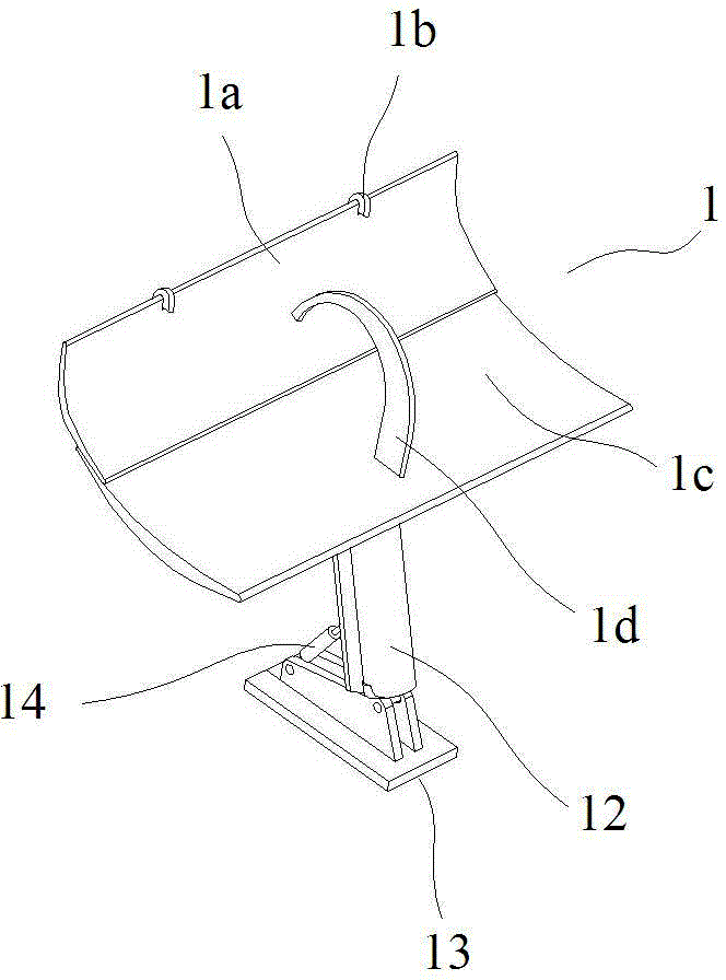
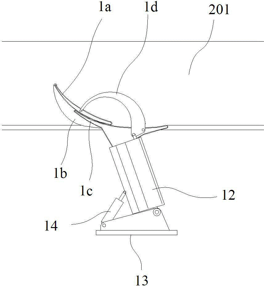
[0026] like Figure 1 to Figure 8 In the shown embodiment, a multi-piece tail structure includes two tail devices 1, air flow channels 201 and hydraulic pipelines, wherein the tail device is arranged at the rear 2 of the car, and the two tail devices are arranged along the middle of the car. Axisymmetric arrangement. The airflow channel is located at the rear of the car, with openings facing upwards. There is one on the left and right sides, corresponding to the rear wing device. The airflow flowing through the upper part of the vehicle body will flow to the rear of the car along the airflow channel. The empennage device is located at the end of the airflow passage, and includes a main wing 1c, an aileron 1a and a drive mechanism, the main wing and the aileron are arranged in parallel, and the main wing is located below the aileron. The middl...


PUM


Abstract

The invention discloses a multiple-piece tail wing structure which comprises two tail wing devices, airflow channels and a hydraulic pipeline. The tail wing devices are arranged at the tail ends of the airflow channels respectively. Each tail wing device comprises a main wing, an auxiliary wing and a driving mechanism. The main wing is arranged under the auxiliary wing; the middle portion of the main wing is provided with a plurality of auxiliary wing positioning plates extending upwards; the upper ends of the auxiliary wing positioning plates are hinged with the tail end of the auxiliary wing; the front end of the auxiliary wing is close to the tail end of the main wing; the middle portion of the main wing is provided with a rotation plate which is vertically arranged and can rotate with respect to the main wing; and the other end of the rotation plate is hinged with the middle portion of the auxiliary wing. The driving mechanism comprises a main wing cylinder, an auxiliary wing cylinder, a rotation assisting cylinder and a base. The hydraulic pipeline comprises a hydraulic pump, a main wing pipeline, an auxiliary wing pipeline and a rotation assisting pipeline. The invention is to provide the multiple-piece tail wing structure which is capable of adjusting air resistance and downward pressure applied to the left and right two sides of the tail portion of an automobile so as to improve automobile adhesion performance and reduce tyre load.

Description

technical field [0001] The invention belongs to the field of automobiles, in particular to a multi-piece tail structure. Background technique [0002] During the driving process of the car, due to the shape and structure characteristics of the car itself, the car will generate an upward lift when driving, and the adhesion between the car and the ground will decrease. When the car is running at a high speed, this phenomenon is more prominent. In order to alleviate the negative impact of lift on the driving stability of the car as much as possible, designers often start from the shape of the car and optimize the shape of the car to reduce the lift generated. In addition, on high-performance cars, sports cars or racing cars, in order to improve the adhesion of the car to the ground when cornering, a front wing or tail will be installed on the head or tail of the car. The cross-sectional shape of the wing is similar, but its installation method is just opposite to that of the a...

Claims


Application Information

Patent Timeline
IPC IPC(8): B62D35/00B62D37/02
CPCY02T10/82B62D35/007B62D37/02
Inventor 孙永剑刘东升喻立军
Owner ZHEJIANG SCI-TECH UNIV
Why Eureka
Try Eureka