Electronic-gyroscope-autostabilization trailing arm electric damping active suspension damping device

An electronic gyroscope and electric damping technology, which is applied in suspension, elastic suspension, transportation and packaging, etc., can solve the problems of small shock absorbing movement stroke, occupying the space at the bottom of the axle, and many components, so as to achieve stable body and increase Attitude stability, the effect of suppressing body sway

Inactive Publication Date: 2014-05-07
邹帆
View PDF4 Cites 4 Cited by
  • Summary
  • Abstract
  • Description
  • Claims
  • Application Information

AI Technical Summary

Problems solved by technology

[0002] Existing automobile active suspension devices include air suspension, oil-pneumatic spring (electro-hydraulic type), electromagnetic suspension, etc.; all have the disadvantages of complex mechanism, many components, and small shock-absorbing movement stroke; these suspension devices mostly use hydraulic damping elements, The damping coefficient and characteristic frequency of the hydraulic damping element are determined by the shape and size of the damping element and the physical characteristics of the hydraulic oil. It has a sharp amplitude-frequency response characteristic and is suitable for a narrow frequency range. The designed shock absorption effect can be achieved under the specified speed, road surface conditions and specified load conditions, which limits the performance of the active suspension device.
Moreover, all these active suspension devices cannot recover the energy of road impact and vibration, and do not have energy-saving effects.
In order to detect the posture of the vehicle body, some active damping systems use ultrasonic sensors to detect the distance from the chassis to the ground. These methods are greatly affected by the road medium, and the application effect is not ideal.
[0003] Existing automobile suspension devices mostly use transverse cantilever or transverse link restraint, which limits the movement stroke of the shock absorber and occupies the bottom space of the axle, which limits the passing capacity of the vehicle

Method used


Image

  • Electronic-gyroscope-autostabilization trailing arm electric damping active suspension damping device
  • Electronic-gyroscope-autostabilization trailing arm electric damping active suspension damping device

Examples


Embodiment Construction

[0014] The present invention is described in further detail below in conjunction with accompanying drawing:

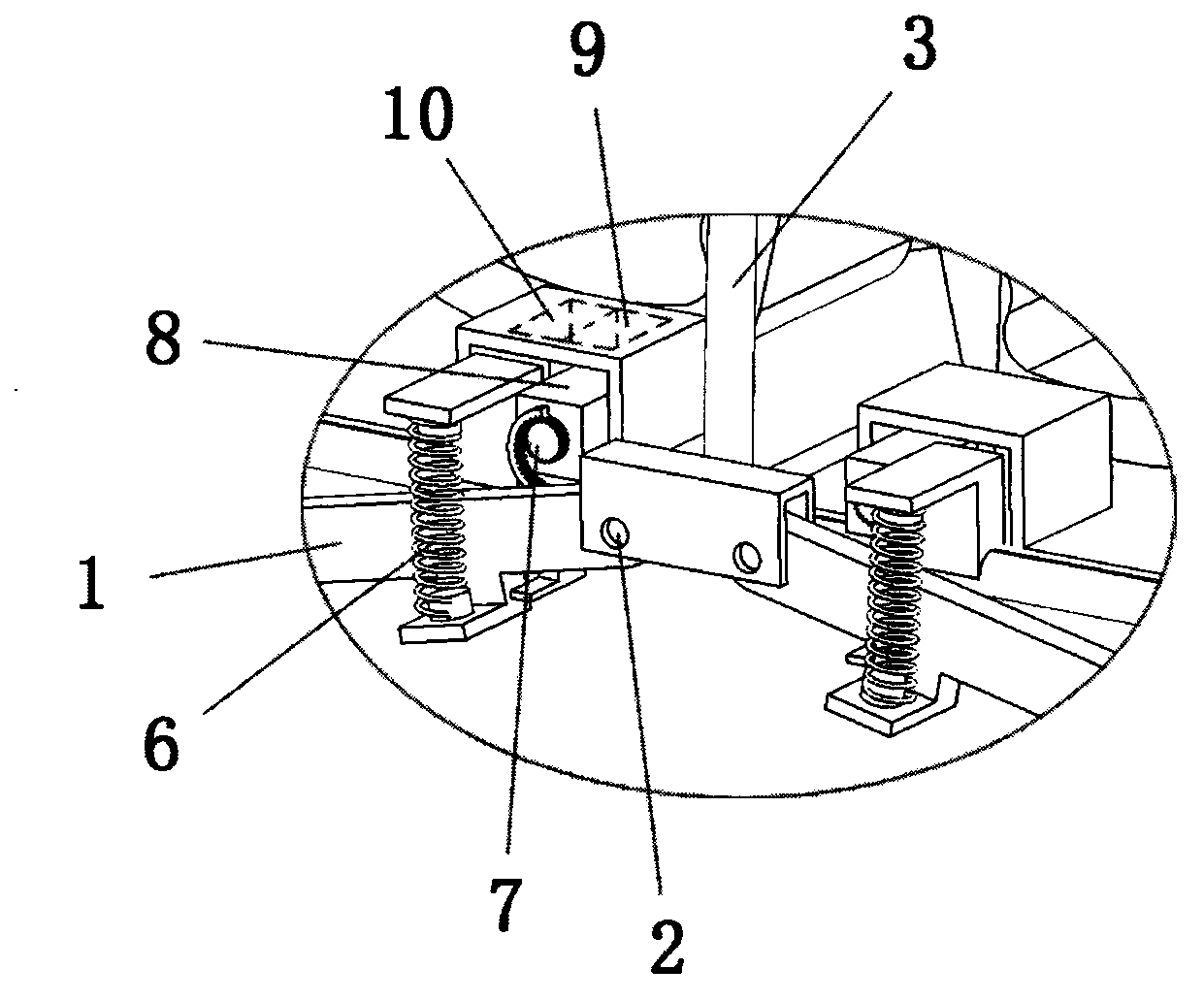
[0015] Such as figure 1 , figure 2 As shown, an electronic gyro stabilized trailing arm electric damping active suspension shock absorber includes a cantilever 1, one end of the cantilever 1 is fixed on the vehicle frame 3 through a bearing 2, and the other end is connected to the wheel 5 through a flange 4; A damping spring 6 is installed between the cantilever 1 and the frame 3, and the load of the frame 3 is transmitted to the cantilever 1 and the wheel 5 through the spring 6; during the shock-absorbing movement, the cantilever 1 swings up and down around the bearing 2 in a circle, and its circumferential plane Coincides with the direction of travel of the vehicle;

[0016] The transmission gear 7 is installed near the fixed end of the cantilever 1 and the vehicle frame 3 and connected to the damping motor 8 and the motor controller 9. The transmission gear 7 tra...


PUM


Abstract

The invention discloses an electronic-gyroscope-autostabilization trailing arm electric damping active suspension damping device which comprises a cantilever. One end of the cantilever is fixed on a car frame through a bearing, and the other end of the cantilever is connected with a wheel through a flange. A damping spring is arranged between the cantilever and the car frame. A transmission gear is arranged close to a fixing end of the car frame and the cantilever, a damping motor and a motor controller are connected, and the car frame is fixedly provided with an electronic gyroscope for detecting the car body gesture.

Description

technical field [0001] The invention relates to an electric vehicle shock absorber, in particular to an electronic gyro stabilized trailing arm electric damping active suspension shock absorber. Background technique [0002] Existing automobile active suspension devices include air suspension, oil-pneumatic spring (electro-hydraulic type), electromagnetic suspension, etc.; all have the disadvantages of complex mechanism, many components, and small shock-absorbing movement stroke; these suspension devices mostly use hydraulic damping elements, The damping coefficient and characteristic frequency of the hydraulic damping element are determined by the shape and size of the damping element and the physical characteristics of the hydraulic oil. It has a sharp amplitude-frequency response characteristic and is suitable for a narrow frequency range. The designed shock absorption effect can be achieved under certain speed, road surface conditions and specified loading conditions, wh...

Claims


Application Information

Patent Timeline
IPC IPC(8): B60G17/015
CPCB60G2200/132
Inventor 邹帆
Owner 邹帆
Why Eureka
Try Eureka