
Gripper

A technology of grippers and workpieces, applied in the direction of manipulators, chucks, manufacturing tools, etc., can solve problems such as workpiece deformation, inability to adjust the assembly process in a timely manner, and force conditions that cannot be monitored

Active Publication Date: 2015-08-12
TSINGHUA UNIV +1
View PDF8 Cites 4 Cited by
  • Summary
  • Abstract
  • Description
  • Claims
  • Application Information

AI Technical Summary

Problems solved by technology

Most of the current grippers are rigidly connected, and the grippers directly contact the workpiece rigidly, so that if there is force during the assembly process, it is easy to cause deformation of the workpiece; and the force of the assembly process cannot be monitored, and it is impossible to accurately know the direction of the workpiece during the assembly process Due to the large force, it is impossible to adjust the assembly process in a timely manner

Method used


Image

  • Gripper
  • Gripper
  • Gripper

Examples


Embodiment Construction

[0045] The gripper according to the present invention will be described in detail below with reference to the accompanying drawings.

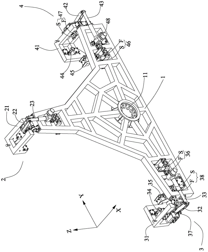
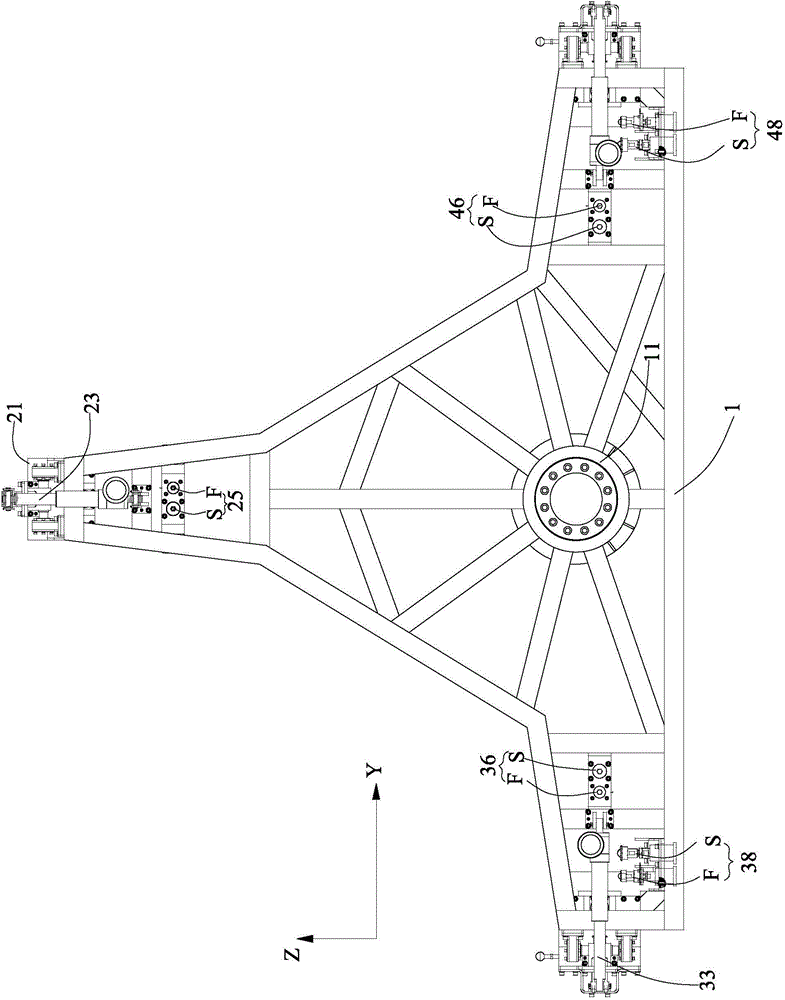
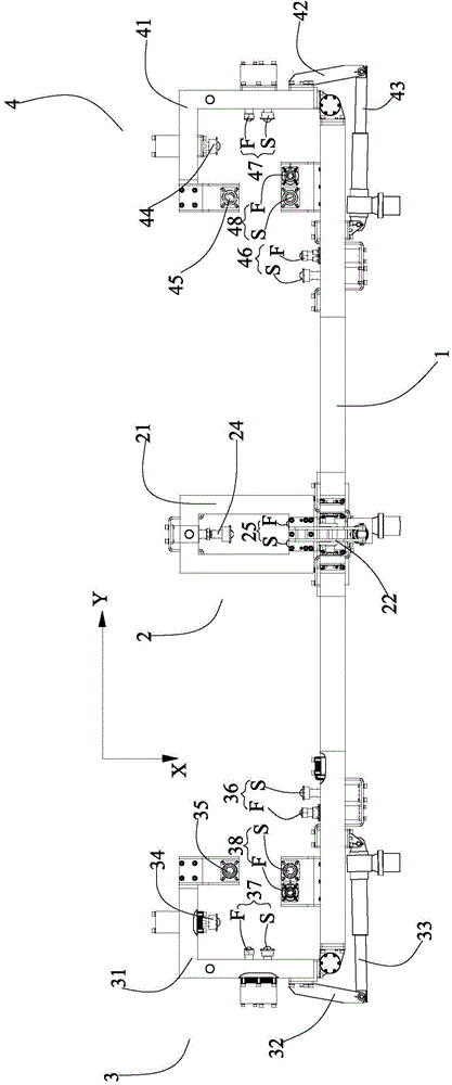
[0046] refer to Figure 1 to Figure 5 , The gripper according to the present invention includes a body 1 , an upper gripper assembly 2 , a left gripper assembly 3 and a right gripper assembly 4 .

[0047] The upper gripper assembly 2 includes: an upper main body 21, which is pivotally connected to the upper end of the body 1; an upper pivotal connecting arm 22, one end of which is fixedly connected to the upper telescopic link 23 of the upper main body 21, and one end which is pivotally connected to The other end of the upper pivotal connecting arm 22 is fixedly connected to the body 1 and can be stretched; the upper X-direction support spring body 24 is arranged on the upper body 21 and can be elastically stretched for elastic contact and clamping in the X direction Or loosen the workpiece; the upper side X-direction force-measuring support s...


PUM


Abstract

The invention provides a grippe. The gripper comprises a body, an upper side gripper assembly, a left side gripper assembly and a right side gripper assembly. The upper side gripper assembly comprises an upper side body, an upper side pivoting connection arm, an upper side telescopic connection rod, an upper side X-direction bearing spring body and an upper side X-direction side force bearing spring body. The left side gripper assembly comprises a left side body, a left side pivoting connection arm, a left side telescopic connection rod, a left side X-direction bearing spring body, a left side Z-direction bearing spring body, a left side X-direction side force bearing spring body, a left side Y-direction side force bearing spring body and a left side Z-direction side force bearing spring body. The right side gripper assembly comprises a right side body, a right side telescopic connection rod, a right side X-direction bearing spring body, a right side Z-direction bearing spring body, a right side X-direction side force bearing spring body, a right side Y-direction side force bearing spring body and a right side Z-direction side force bearing spring body. Thus, assembly force applied to a workpiece in the assembly process can be passively and flexibly monitored.

Description

technical field [0001] The invention relates to a gripper, in particular to a flexible gripper which can realize passive flexibility and monitor the assembly force in the assembly process of workpieces, and is used for grasping, moving and assembling large parts that cannot be deformed by force. Background technique [0002] With the continuous development of science and technology, more and more enterprises use automation technology to replace traditional manual operations in the fields of assembly and transportation to improve efficiency and save costs. In the field of automated production, robots or manipulators operate through end effectors, and in the field of workpiece assembly, grippers are the most widely used end effectors. Most of the current grippers are rigidly connected, and the grippers directly contact the workpiece rigidly, so that if there is force during the assembly process, it is easy to cause deformation of the workpiece; and the force of the assembly pr...

Claims


Application Information

Patent Timeline
Patent Type & Authority Applications(China)
IPC IPC(8): B25J15/10B25J15/12
CPCB25J15/10B25J15/12
Inventor 徐静万安陈恳刘志谢颖
Owner TSINGHUA UNIV
Learn More