Detachable hobbing device for roller screen

A technology for dismantling devices and roller sieves, which is applied in the fields of filter screens, solid separation, chemical instruments and methods, etc. It can solve the problems of large assembly errors, time-consuming and labor-intensive replacement process, and affect the service life, so as to save time and effort in the replacement process Effect

Active Publication Date: 2015-08-12
山东新特能源装备科技有限公司
View PDF4 Cites 3 Cited by
  • Summary
  • Abstract
  • Description
  • Claims
  • Application Information

AI Technical Summary

Problems solved by technology

[0002] Coal mine roller screen is a device that arranges rolling shafts with multiple hobbing teeth horizontally in rows to form a rolling screen surface and drives the rollers to rotate through chains. The hobbing teeth on the rolling shafts are set at intervals through spacers. The particles are sent to the front end of the rotating rolling screen, and the fine coal particles fall through the sieve holes formed between the rolling shafts on the rolling screen surface or between two hobs, and the remaining large particles will pass through the rotating hobs or The spacer sleeve is pushed to the end of the rolling screen to leave the rolling screen surface. During the screening process, when it is necessary to replace the worn or damaged hobbing gear, because the hobbing gear adopts an integral structure, it is necessary to disassemble the gear at the end of the rolling shaft first. bearing housing, then remove the spacer and hobs, especially when the hobs in the middle of the roller need to be replaced, more hobs and spacers need to be removed one by one along the roller, and then the complete hob Replace them, and finally restore and install the removed hobs and spacers. The entire replacement process is time-consuming and laborious. The connection has been fully run-in, if the restoration sequence is improper, it will lead to large assembly errors and affect the service life

Method used


Image

  • Detachable hobbing device for roller screen
  • Detachable hobbing device for roller screen
  • Detachable hobbing device for roller screen

Examples


Embodiment Construction

[0016] The present invention is described in detail below in conjunction with accompanying drawing and specific embodiment:

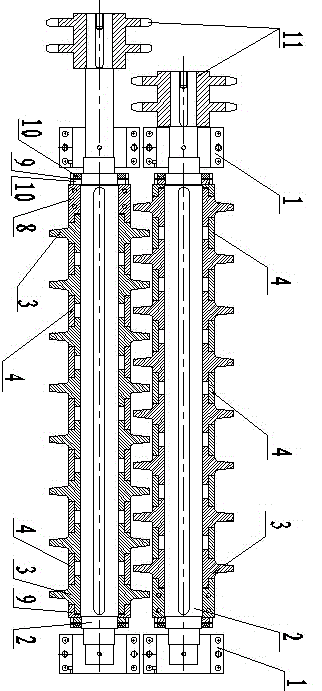
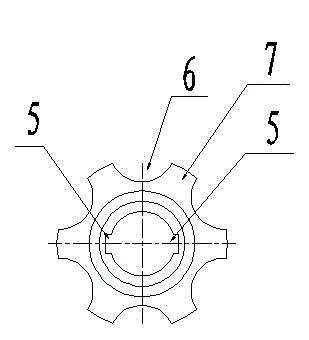
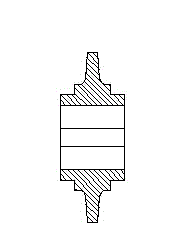
[0017] Such as Figure 1-5 Shown is a specific embodiment of the present invention, the detachable gear hobbing device for the roller screen, including the rollers 2 arranged at both ends of the roller screen support through the bearing housing 1, and the sub-units connected to the rollers 2 in turn. The one-piece hobbing gear 3 also includes a long fixing sleeve 8 and a short fixing sleeve 9 respectively arranged at both ends of the roller shaft 2, and a spacer sleeve 4 arranged between adjacent split-type hobbing gears 3. The stop device for the axial movement of the fixed sleeve, the inner sides of the long and short fixed sleeves are respectively pressed against the outer sides of the ends of the split hob 3, and the inner sides of the two ends of the spacer sleeve 4 are respectively connected to the outer ends of the split hob 3. Press and fit eac...


PUM


Abstract

The invention discloses a detachable hobbing device for a roller screen. The detachable hobbing device for the roller screen comprises rollers 2 which are arranged at the two ends of a roller screen support through bearing pedestals 1, split type hobbing teeth 3 which are sequentially connected to the rollers 2, and distance sleeves 4 which are arranged between the adjacent split type hobbing teeth 3. Detachable devices are arranged between the split type hobbing teeth 3 and the rollers 2. When the hobbing teeth need to be replaced, the interconnection of the hobbing teeth, the rollers and the distance sleeves is relieved through the detachable devices. Due to the fact that the split type hobbing teeth 3 are designed, the hobbing teeth needing to be replaced are separated directly so that novel hobbing teeth can be mounted, other distance sleeves and hobbing teeth do not need to be removed from the rollers one by one any more, time and labor are saved in the replacing process, meanwhile, recovery assembly of the hobbing teeth or the distance sleeves and the rollers is avoided, and the problem that the service life is shortened due to assembly errors can be solved.

Description

technical field [0001] The invention relates to the field of coal mine equipment, in particular to a detachable hobbing device for roller screens. Background technique [0002] Coal mine roller screen is a device that arranges rolling shafts with multiple hobbing teeth horizontally in rows to form a rolling screen surface and drives the rollers to rotate through chains. The hobbing teeth on the rolling shafts are set at intervals through spacers. The particles are sent to the front end of the rotating rolling screen, and the fine coal particles fall through the sieve holes formed between the rolling shafts on the rolling screen surface or between two hobs, and the remaining large particles will pass through the rotating hobs or The spacer sleeve is pushed to the end of the rolling screen to leave the rolling screen surface. During the screening process, when it is necessary to replace the worn or damaged hobbing gear, because the hobbing gear adopts an integral structure, it...

Claims


Application Information

Patent Timeline
IPC IPC(8): B07B1/46
CPCB07B1/46
Inventor 王茂桐李庆云陈开鹏聂根磊宋西国姚健王克斌董仕奎张传成房洪翠
Owner 山东新特能源装备科技有限公司
Why Eureka
Try Eureka