


Quick Research
Generate reliable direction feasibility study reports for your R&D in just a few steps.

Technical Q&A
Discover and master advanced knowledge NOW. Basics, ideas, possibilities, all at once.

Find Solutions
As an expert in R&D theories, this can generate solutions to your technical problems instantly.

Evaluate Feasibility
Analyze your overall solution with one click, know your potential R&D risks in advance.

Monitor Landscape
Get weekly tech updates, stay abreast of the latest tech innovations and key insights.
Cassette and analyzer device
A test box and analyzer technology, applied in the field of test boxes, can solve problems such as destructive testing
- Summary
- Abstract
- Description
- Claims
- Application Information
AI Technical Summary
Problems solved by technology
Method used
Image


Examples
Embodiment Construction
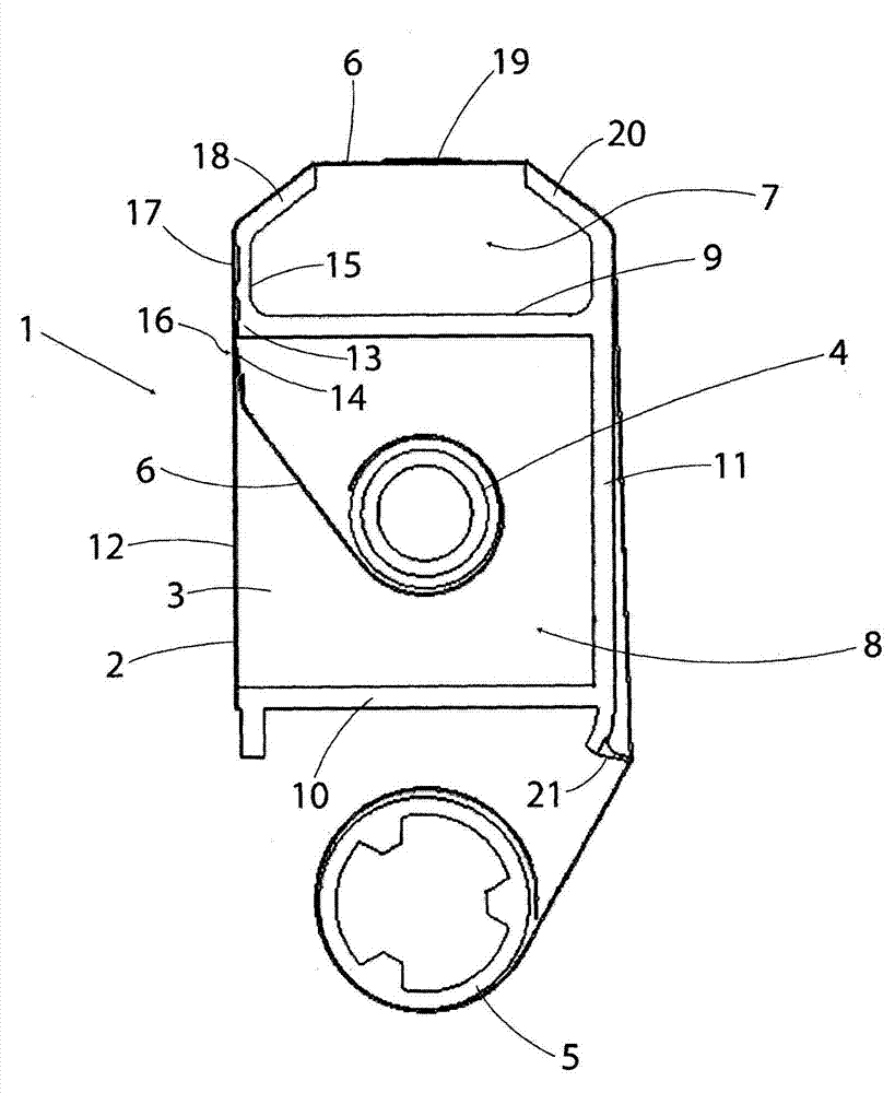
[0054] first reference figure 1 , the part of the test cartridge 1 shown is in the form of a housing 2 comprising a body 3 with a supply reel 4 and a recovery reel 5 . Belt 6 extends from supply reel 4 , through test zone 7 , onto take-up reel 5 .
[0055] The supply reel 4 is located in a supply chamber 8 delimited by a front wall 9 , a rear wall 10 and side walls 11 . The other side wall 12 serves to close the chamber 8 . A wall 12 is fixed to the rear wall 10 and protrudes beyond an end 13 of the front wall 9 so as to define a small gap 14 between the wall 12 and the front wall 9 for the strip 6 to leave the chamber 8 .
[0056] Elongated fingers 15 protrude from the front wall 9, and the wall 12 is arranged in close proximity to the fingers 15 to hold the seal 16 against when the strap 6 is pulled through the channel 17 between the wall 12 and the fingers 15. Lean on belt 6. The fingers 15 terminate in guides 18 at an angle towards the test zone 7 to guide the tape 6 i...
PUM
 Abstract
Description
Claims
Application Information
 - R&D Engineer
- R&D Manager
- IP Professional
- Industry Leading Data Capabilities
- Powerful AI technology
- Patent DNA Extraction
Browse by: Latest US Patents, China's latest patents, Technical Efficacy Thesaurus, Application Domain, Technology Topic, Popular Technical Reports.
© 2024 PatSnap. All rights reserved.Legal|Privacy policy|Modern Slavery Act Transparency Statement|Sitemap|About US| Contact US: help@patsnap.com