
Portable electronic device and camera module set thereof

A technology for electronic devices and camera modules, which is applied to cameras, camera bodies, televisions, etc., can solve the problems of inability to provide accommodation space for camera modules, unfavorable miniaturization design of portable devices, and hidden dangers of high-end camera modules. , to achieve the effect of facilitating high pixel design, miniaturization design, and reducing electromagnetic interference

Inactive Publication Date: 2015-07-29
NANCHANG O FILM OPTICAL ELECTRONICS TECH CO LTD +3
View PDF4 Cites 20 Cited by
  • Summary
  • Abstract
  • Description
  • Claims
  • Application Information

AI Technical Summary

Problems solved by technology

[0003] However, for high-pixel camera modules, the overall height of the camera module has always been a big problem, because the higher the pixel, the more lenses are required, and the corresponding height is greater. As portable electronic devices become thinner and thinner , which cannot provide a large accommodation space for the camera module, so that the volume of the camera module is greatly limited
Therefore, for high-pixel camera modules, if traditional camera modules use high-precision lenses, it is not conducive to the miniaturization design of portable devices.
[0004] In addition, the plastic bracket of the traditional camera module is affected by the material. The wall thickness of the injection molded product is generally only 0.3mm at the thinnest, and because the wall thickness is too thin, the molding is easy to break, deform, and less material. Light leakage is prone to occur on the module
In addition, the high-pixel sensor has very strict requirements on the assembly inclination. The plastic bracket is affected by the material, the fluidity is unstable, and the flatness is difficult to control. It will be a great hidden danger to the image of high-end camera modules.

Method used


Image

  • Portable electronic device and camera module set thereof
  • Portable electronic device and camera module set thereof
  • Portable electronic device and camera module set thereof

Examples


Embodiment Construction

[0037] In order to facilitate the understanding of the present invention, the present invention will be described more fully below with reference to the associated drawings. Preferred embodiments of the invention are shown in the accompanying drawings. However, the present invention can be embodied in many different forms and is not limited to the embodiments described herein. On the contrary, these embodiments are provided to make the understanding of the disclosure of the present invention more thorough and comprehensive.

[0038] It should be noted that the terms "vertical", "horizontal", "left", "right" and similar expressions used herein are for illustrative purposes only.

[0039] Unless otherwise defined, all technical and scientific terms used herein have the same meaning as commonly understood by one of ordinary skill in the technical field of the invention. The terms used herein in the description of the present invention are for the purpose of describing specific ...


PUM

PropertyMeasurementUnit
Depthaaaaaaaaaa
Depthaaaaaaaaaa
Depthaaaaaaaaaa

Abstract

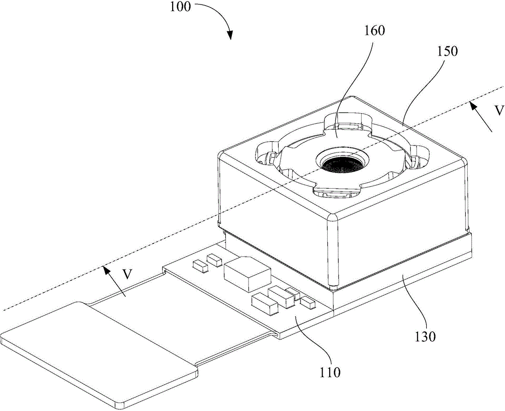
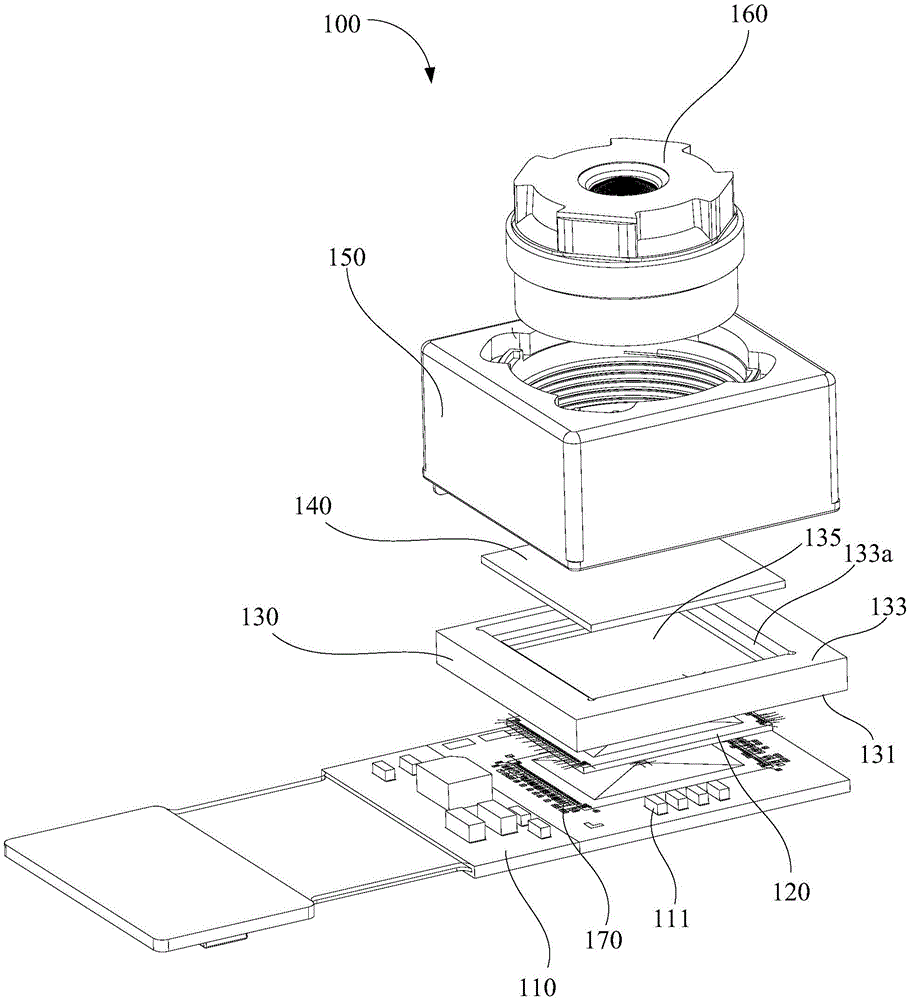
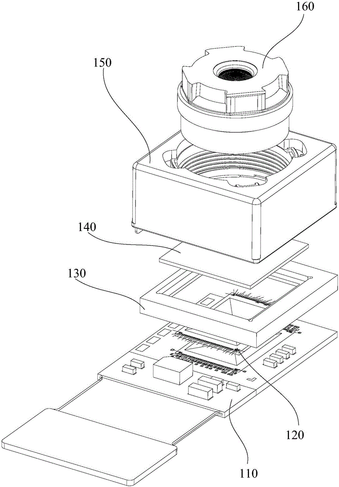
The invention discloses a portable electronic device and a camera module set thereof. The camera module set comprises a flexible circuit board which is adopted as a carrier, a sensor which is arranged on the flexible circuit board and is electrically connected with the flexible circuit board, an aluminum bracket which is arranged on the flexible circuit board and covers the sensor from above, and an infrared cut-off filter; the aluminum bracket comprises a first surface and a second surface which is opposite to the first surface; a photosensitive window which penetrates the first surface and the second surface is formed at the middle of the aluminum bracket; the first surface and the second surface are respectively provided with a first step groove and a second step groove which surround the photosensitive window by one turn; the first step groove is provided with a bottom surface which is opposite to the flexible circuit board; the second step groove is provided with a bearing surface which is parallel to the bottom surface of the first step groove; the bearing surface is separated from the bottom surface by a distance smaller than 0.3 mm; and the infrared cut-off filter is accommodated in the second step groove and abuts against the bearing surface. With the camera module set of the portable electronic device adopted, the miniaturization and high-pixel design of the portable electronic device can be benefitted, and image pickup performance can be improved.

Description

【Technical field】 [0001] The invention relates to a photographable electronic device, in particular to a portable electronic device and a camera module thereof. 【Background technique】 [0002] Portable electronic devices are usually equipped with a camera module for the convenience of taking pictures. For example, a high-end mobile phone has a camera module on the rear shell or the front shell. Traditional camera module brackets usually use plastic brackets, which are adopted by most manufacturers due to their advantages of low cost and easy molding. [0003] However, for high-pixel camera modules, the overall height of the camera module has always been a big problem, because the higher the pixel, the more lenses are required, and the corresponding height is greater. As portable electronic devices become thinner and thinner , which cannot provide a large accommodating space for the camera module, so that the volume of the camera module is greatly limited. Therefore, for a ...

Claims


Application Information

Patent Timeline
IPC IPC(8): H04N5/225G03B17/12
Inventor 齐书申成哲晏政波
Owner NANCHANG O FILM OPTICAL ELECTRONICS TECH CO LTD
Learn More