
A Method for Fusion of Infrared Image and Visible Light Image Based on Guided Filtering

A guided filtering, infrared image technology, applied in image enhancement, image analysis, image data processing and other directions, can solve the problems of lack of translation invariance, image block effect, no anisotropy, etc., to meet translation invariance, Efficiently obtain and avoid the effect of ringing effect

Active Publication Date: 2018-07-27
ORDNANCE TECH RES INST OF THE GENERAL ARMAMENT DEPT PLA
View PDF3 Cites 1 Cited by
  • Summary
  • Abstract
  • Description
  • Claims
  • Application Information

AI Technical Summary

Problems solved by technology

Multi-scale analysis methods represented by wavelet transform and pyramid decomposition have achieved great success in the fusion of infrared and visible light images, but these two algorithms also have their own shortcomings and deficiencies: pyramid decomposition makes the data between different levels relevant, The size of the image after pyramid decomposition is 4 / 3 of the source image, which increases the amount of data and may introduce false information; while the wavelet transform only has three high-frequency direction information of horizontal, vertical and diagonal, which is not anisotropic and cannot Accurately express the edge and line features of the image, and due to the lack of translation invariance, there is a blocky effect at the edge of the image
At present, the widely used non-linear filtering is bilateral filtering, but when bilateral filtering has many similar pixels around a pixel (usually near the edge), the Gaussian average weight is unstable, and unwanted contours will be generated at the edge, and bilateral Filtering is computationally inefficient

Method used


Image

  • A Method for Fusion of Infrared Image and Visible Light Image Based on Guided Filtering
  • A Method for Fusion of Infrared Image and Visible Light Image Based on Guided Filtering
  • A Method for Fusion of Infrared Image and Visible Light Image Based on Guided Filtering

Examples


Embodiment Construction

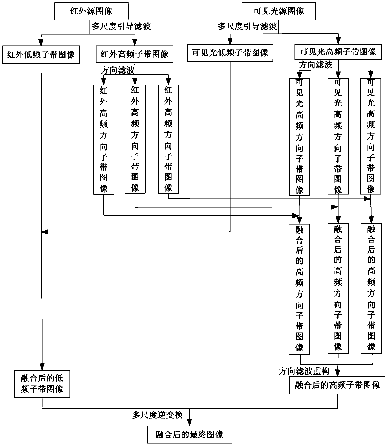
[0041] The present invention will be further described in detail below with reference to the accompanying drawings and embodiments. In an embodiment of the present invention, an infrared image and a visible light image are fused. Such as figure 1 As shown, the specific implementation steps are as follows:

[0042] Step 1. Extend guided filtering to multi-scale, perform guided filtering iteratively, and perform multi-scale guided filtering decomposition on source images (including visible light source images and infrared source images) to obtain low-frequency sub-band images and high frequency subband images Among them, i and j are the positions of image pixels, is the visible light low-frequency sub-band image, is the infrared low-frequency sub-band image, is the visible light high-frequency sub-band image, is the infrared high-frequency sub-band image, and L is the scale number of decomposition, or the number of layers of decomposition.

[0043] Guided filtering ...


PUM


Abstract

The invention provides an infrared image and visible image fusion method based on guide filtering. The method comprises the steps of: firstly, expanding the guide filtering to multiple scales, and performing multi-scale decomposition on an infrared image and a visible image by using the multi-scale guide filtering, so as to obtain a low-frequency subband and a high-frequency subband; performing nonsubsampled directional filtering on the high-frequency subband, so as to obtain a directional subband coefficient; applying different fusion rules to the directional subband coefficient and a low-frequency subband coefficient, so as to obtain the corresponding directional subband coefficient and the low-frequency subband coefficient after fusion, and finally, performing directional filtering reconstruction and multi-scale reverse transformation based on the guide filtering, so as to obtain a final fusion image. According to a fusion result obtained by adopting the method, the edge and thermal radiation characteristics of an infrared image object are preferably kept, scene details of the visible image can be preferably reserved, and the information content of a fusion image is increased, so that the edge and details of the fusion image are enriched.

Description

technical field [0001] The invention relates to the technical field of image information processing, in particular to a method for fusing infrared images and visible light images based on guided filtering. Background technique [0002] Multi-sensor image fusion technology refers to the image of the same scene obtained by different sensors or the images of the same scene obtained by the same sensor at different times, after denoising, temporal registration, spatial registration and resampling, and then using a certain Fusion technology is the process of obtaining a composite image. Compared with the information of a single sensor signal, since the information provided by multiple sensor signals is redundant and complementary, the fusion of multi-source information can overcome the limitations of a single sensor in terms of spectrum and spatial resolution. Limitations, to obtain better quality images that contain feature information of each source image, to maximize the infor...

Claims


Application Information

Patent Timeline
Patent Type & Authority Patents(China)
IPC IPC(8): G06T7/00G06T5/50
CPCG06T5/002G06T2207/10048G06T2207/20024G06T2207/20221
Inventor 陈志斌刘先红肖文健宋岩肖程秦梦泽
Owner ORDNANCE TECH RES INST OF THE GENERAL ARMAMENT DEPT PLA
Learn More