Eureka AIR delivers breakthrough ideas for toughest innovation challenges, trusted by R&D personnel around the world.

A 3D Coordinate Measurement Method Based on Ray Angle Calibration

A technology of light angle and measurement method, which is applied in the direction of measuring device, optical device, image data processing, etc., can solve the problems of not being able to realize fast measurement, fast and real-time, etc., and achieve low hardware requirements, high accuracy of measurement results, The effect of simple system structure

Inactive Publication Date: 2017-05-10
SICHUAN UNIV
View PDF9 Cites 0 Cited by
  • Summary
  • Abstract
  • Description
  • Claims
  • Application Information

AI Technical Summary

Problems solved by technology

The plane calibration method proposed by Zhang is currently the most widely used two-dimensional plane calibration method. This method has high calibration accuracy and is easy to implement. However, during the calibration process, it needs to take multiple images of poses and cannot achieve fast measurement.
[0003] In the three-dimensional measurement method, neither the coordinate measurement based on camera block calibration proposed by Jia Zhenyuan et al. nor the traditional three-coordinate machine measurement method can solve the fast and real-time problem. In order to overcome the above shortcomings, the present invention proposes a Three-dimensional Coordinate Measurement Method Based on Ray Angle Calibration

Method used


Image

  • A 3D Coordinate Measurement Method Based on Ray Angle Calibration
  • A 3D Coordinate Measurement Method Based on Ray Angle Calibration
  • A 3D Coordinate Measurement Method Based on Ray Angle Calibration

Examples


Embodiment Construction

[0017] The present invention will be described in more detail below in conjunction with the accompanying drawings and specific embodiments.

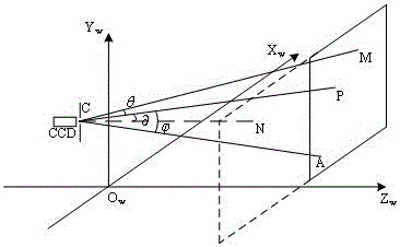
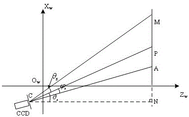
[0018] A three-dimensional coordinate measurement method based on light angle calibration, the system model is as follows figure 1 As shown, the display is used as its calibration surface, and the black and white checkerboard plane with grayscale values ​​of 255 and 0 is used as a template, and a checkerboard with an appropriate size is designed according to the screen size and resolution of the display. The display is parallel to X in the world coordinate system w o w Y w Surface, the Z of all pixels on it w Coordinates are fixed values. In order to eliminate the influence of pupil aberration on the system, a diaphragm is set near the lens.

[0019] Step 1: Measure the coordinates of feature points on the external aperture and the plane calibration target

[0020] Add an external light hole in front of the camera lens, measure the...


PUM


Abstract

The invention discloses a three-dimensional coordinate measurement method based on light ray angle calibration. The method includes the steps of firstly, measuring coordinates of an external aperture and the upper angular point of a target with a two-dimensional checkerboard reference object as a calibration target; secondly, projecting light ray passing through the aperture through the angular point to all planes of a world coordinate system, and calculating the included angle between the light ray and the optical axis of a camera; thirdly, shooting a single image, obtaining coordinates of a lower angular point of an image coordinate system through a Harris angular point detection algorithm, and obtaining the included angles between the light rays, passing through the aperture, of all pixel points on the CCD target face and the optical axis according to the pinhole camera principle with pixels as unit interpolations; fourthly, calculating spatial coordinates of any point on the calibration target face through the angle matrix. The requirement of the method for devices is low, the system structure is simple, the measurement result has high accuracy, and real-time measurement can be completed.

Description

technical field [0001] The invention relates to a three-dimensional coordinate measuring method based on light angle calibration. Background technique [0002] Optical 3D measurement methods are widely used in machine vision, industrial inspection, biomedicine and many other fields. In the field of optical three-dimensional measurement, in order to obtain the three-dimensional coordinates of the object to be measured, the camera will be calibrated first, and the accuracy of the calibration will directly affect the final measurement accuracy. Camera calibration requires the help of targets with known parameters, which can be divided into two types according to their types: two-dimensional planar targets and three-dimensional three-dimensional targets. Using a three-dimensional stereo target to calibrate the camera, the calibration process is simple and the accuracy of the result is high. However, due to the high production cost of the three-dimensional stereo target and the ...

Claims


Application Information

Patent Timeline
Patent Type & Authority Patents(China)
IPC IPC(8): G01B11/00G01B11/03G06T7/00
Inventor 李大海代贞强杨丽杰李成旭鄂可伟
Owner SICHUAN UNIV
Why Eureka
Eureka Blog
Learn More