
Forced LNG (Liquefied Natural Gas) evaporator for ships

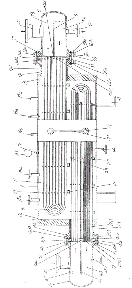
A forced evaporation, marine technology, applied to pressure vessels, container discharge methods, equipment discharged from pressure vessels, etc., can solve the problem of low gasification efficiency and capacity of LNG, damage to evaporation tubes, and large volume of gasification devices To achieve the effect of improving heat dissipation and gasification efficiency, saving installation and use space, and simplifying the overall structure

Active Publication Date: 2015-07-29
JIANGSU YUTE ENERGY EQUIP
View PDF12 Cites 5 Cited by
  • Summary
  • Abstract
  • Description
  • Claims
  • Application Information

AI Technical Summary

Problems solved by technology

[0008] Although the above-mentioned CN203655471U can objectively fulfill the technical effect recorded in paragraph 0011 of its description, the gasification device of this patent has the following shortcomings: First, because it directly uses hot water as the evaporative heat exchange medium to flow through the evaporator tube (patent It is called the gasification of LNG in the finned tube), so on the one hand, it is not conducive to energy saving, and on the other hand, it is unsafe, because the temperature of LNG is usually around -163 ° C, so when directly using hot water to exchange heat outside the evaporation tube, It is easy to damage the evaporation tube due to thermal expansion, resulting in the scrapping of the entire gasification device and even undesired safety accidents; Integrated effect, for example, in the second line of paragraph 0017 of the patent specification, it is mentioned to use 2 to 3 (the patent is 4), so the gasification efficiency and gasification capacity of LNG are relatively low; third, due to the gasification The bulk of the device is not conducive to saving installation space

Method used


Image

  • Forced LNG (Liquefied Natural Gas) evaporator for ships
  • Forced LNG (Liquefied Natural Gas) evaporator for ships

Examples


Embodiment Construction

[0023]In order to enable the examiners of the patent office, especially the public, to understand the technical essence and beneficial effects of the present invention more clearly, the applicant will describe in detail the following in the form of examples, but none of the descriptions to the examples is an explanation of the solutions of the present invention. Any equivalent transformation made according to the concept of the present invention which is merely formal but not substantive shall be regarded as the scope of the technical solution of the present invention.

[0024] In the following descriptions, all concepts involving up, down, left, right, front and rear directionality (or orientation) are for the position state of the picture being described, and the purpose is to facilitate the public Therefore, it cannot be understood as a special limitation on the technical solution provided by the present invention.

[0025] See figure 1 and figure 2 , showing a gasificat...


PUM


Abstract

The invention discloses a forced LNG (Liquefied Natural Gas) evaporator for ships, and belongs to the field of gasification equipment of natural gas. The forced LNG evaporator comprises a tank body of a gasification tank, a group of U-shaped radiating pipes, a group of U-shaped gasification pipes, a radiating-medium guide connector and a gas-liquid guide connector, wherein a left tank-body end cap is arranged at the left end of the tank body, a left tank-body end-cap connector is fixed on the left tank-body end cap, and a left end-cap connector sealing plate is fixed to the left end opening of the left tank-body end-cap connector; a right tank-body end cap is arranged at the right end of the tank body, a right tank-body end-cap connector is fixed to the right tank-body end cap, and a right end-cap connector sealing plate is fixed to the right end opening of the right tank-body end-cap connector; a middle medium inlet opening is formed in the upper part of the tank body of the gasification tank, and a middle medium outlet opening is formed in the bottom of the tank body of the gasification tank; the U-shaped radiating pipes are arranged in the cavity of the tank body; the U-shaped gasification pipes are arranged in the cavity of the tank body; the right end of the radiating-medium guide connector is fixed to one side of the left end-cap connector sealing plate, a radiating-medium guide connector cavity separation plate is arranged in the cavity of the radiating-medium guide connector, a radiating-medium inlet opening is fixed to the upper part of the radiating-medium guide connector, and a radiating-medium outlet opening is fixed to the lower part of the radiating-medium guide connector; a gas-liquid guide separation plate is arranged in the cavity of the gas-liquid guide connector, an LNG inlet opening is fixed to the lower part of the gas-liquid guide connector, and an LNG outlet opening is fixed to the upper part of the gas-liquid guide connector. The forced LNG evaporator is safe, and the radiation efficiency and gasification efficiency are improved; the forced LNG evaporator is convenient to process.

Description

technical field [0001] The invention belongs to the technical field of natural gas gasification devices, and in particular relates to a marine LNG forced evaporator. Background technique [0002] The aforementioned LNG is the abbreviation of "Liquid Natural Gas" in English, and the Chinese name is "Liquefied Natural Gas". other ingredients. LNG is condensed into a liquid by cooling gaseous natural gas to about -163°C under normal pressure. Since its volume is about one-sixth of that of gaseous natural gas, it can significantly save storage and transportation space and cost, and is conducive to long-distance transportation and storage. [0003] The energy source of the marine engine in the prior art still generally uses diesel oil, and when diesel oil burns, it will produce waste gases such as carbon dioxide and other harmful emissions to the environment, and a little carelessness of diesel oil in the process of using the ship will cause floating oil in the waters. pollut...

Claims


Application Information

Patent Timeline
Patent Type & Authority Applications(China)
IPC IPC(8): F17C7/04
Inventor 石美丽杨建
Owner JIANGSU YUTE ENERGY EQUIP
Learn More