
Normally closed solenoid valve with protection device

A technology of normally closed solenoid valve and protection device, applied in valve device, fuel injection device, valve operation/release device, etc., can solve problems such as adverse influence of hydraulic device, damage of hydraulic device, poor safety, etc., to improve strain capacity and work stability, flexible control, protection and safety

Active Publication Date: 2015-07-29
HARBIN ENG UNIV
View PDF6 Cites 1 Cited by
  • Summary
  • Abstract
  • Description
  • Claims
  • Application Information

AI Technical Summary

Problems solved by technology

However, the traditional normally open valve has the following disadvantages: first, when the solenoid valve is faulty and cannot be powered on, the oil drain circuit will always be open, and the normally open valve will not be able to complete the function of controlling fuel flow; second, if the solenoid valve is stuck Dead in the closed state, the oil pressure in the valve will continue to rise, causing adverse effects on the valve and other hydraulic devices connected to the valve, resulting in damage to other hydraulic devices
In short, the safety of the traditional normally open solenoid valve is poor, it is difficult to meet the working stability of the engine, and it does not have the ability to respond to failures in time

Method used


Image

  • Normally closed solenoid valve with protection device
  • Normally closed solenoid valve with protection device
  • Normally closed solenoid valve with protection device

Examples


Embodiment Construction

[0015] Hereinafter, the present invention will be described in more detail with examples in conjunction with the accompanying drawings:

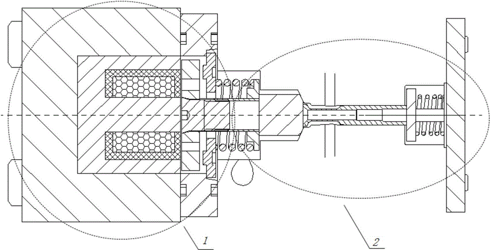
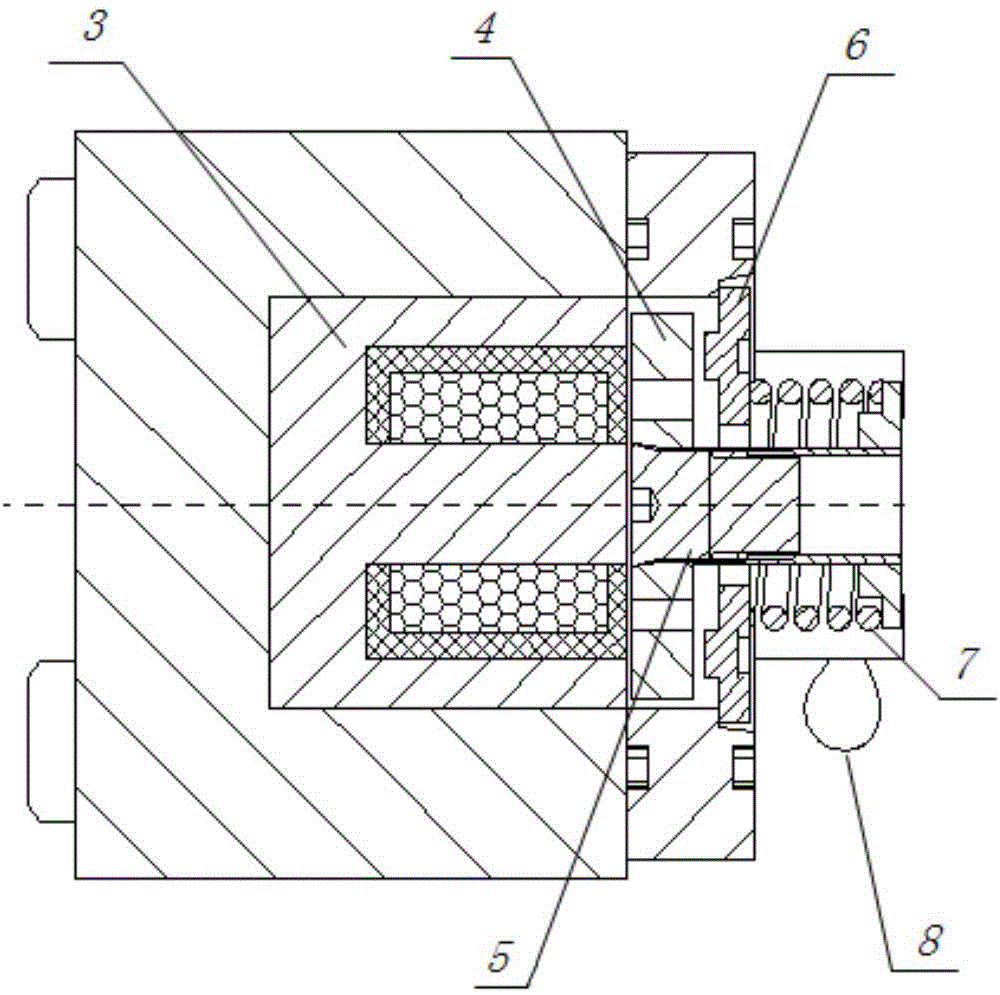
[0016] Combine Figure 1~3 , This device includes solenoid valve 1 and drain valve 2. The solenoid valve 1 includes a solenoid coil 3, an armature 4, a solenoid valve stem 5, a solenoid valve spring seat 6, a solenoid valve spring 7 and an oil drain circuit 8. The drain valve 2 includes a connecting sleeve 9, a drain cone valve 10, an oil inlet oil path 12, a drain valve stem 14 and a drain valve spring 15. The solenoid valve 1 and the drain valve 2 are connected by an interference fit through the solenoid valve stem 5 and the drain valve connecting sleeve 9.

[0017] When the solenoid valve is not powered on, the traditional normally open valve's drain circuit is normally open, and the fuel flows back to the fuel tank through the drain circuit; when the solenoid valve is powered on, the solenoid valve closes the drain circuit, and the fuel can...


PUM


Abstract

The invention aims at providing a normally closed solenoid valve with a protection device. The normally closed solenoid valve comprises a valve body, a solenoid valve part and an oil drain valve part, wherein the solenoid valve part and the oil drain valve part are both arranged on the valve body; the solenoid valve part comprises a solenoid valve shell, an electromagnetic coil, an armature and a valve rod of the solenoid valve; the electromagnetic coil and the armature are mounted in the solenoid valve shell; the valve rod of the solenoid valve is fixed on the armature; the oil drain valve part comprises an oil drain tapered valve, a connection sleeve, a valve rod of an oil drain valve and an oil drain valve spring; the connection sleeve which is provided with a solenoid valve spring at the outer part is in interference fit with the valve rod of the solenoid valve; the connection sleeve is connected with the oil drain tapered valve; the oil drain tapered valve is connected with the valve rod of the oil drain valve; the valve rod of the oil drain valve is arranged in a valve rod sleeve; an oil drain valve spring sleeves the end part of the valve rod of the oil drain valve; the valve body is provided with an oil feeding oil path and an oil drain oil path; the oil feeding oil path and the valve rod sleeve are mutually crossly arranged; the oil drain oil path is communicated to the position of the solenoid valve spring. By virtue of the normally closed solenoid valve with the protection device, the reliability of an engine can be improved.

Description

Technical field [0001] The invention relates to a fuel injection device, specifically an engine fuel injection device. Background technique [0002] With the development and progress of human society, the development of modern engines has to face the dual pressure of energy crisis and environmental pollution. The development of engines tends to use electronic control to control the fuel injection system of the engine. The electromagnetic control valve is a kind of Important technical means. Through electromagnetic control valve control, the engine has the characteristics of high fuel injection pressure and flexible fuel injection timing. [0003] Traditional normally open valve When the solenoid valve is not powered on, the drain oil circuit of the valve is in a normally open state, and the fuel flows back to the tank through the drain oil circuit. When the solenoid valve is powered on, the oil drain circuit is closed by electromagnetic force. At this time, the fuel can often ope...

Claims


Application Information

Patent Timeline
Patent Type & Authority Applications(China)
IPC IPC(8): F16K31/06
CPCF02M51/061F02M61/042F02M61/20F16K31/06
Inventor 范立云闫昕扈爽赵文圣赵建辉王作群刘洋
Owner HARBIN ENG UNIV
Learn More