Hydraulic suspension

A hydraulic mount and pressure plate technology, applied in the direction of shock absorbers, springs, spring/shock absorbers, etc., can solve the problems of unfavorable low-frequency and large-value vibration, decoupling diaphragm damage, dynamic hardening, etc., and achieve favorable isolation Effects of vibration, reduction of suspension dynamic stiffness, and product performance optimization

Inactive Publication Date: 2015-07-29
ANHUI JIANGHUAI AUTOMOBILE GRP CORP LTD
View PDF8 Cites 3 Cited by
  • Summary
  • Abstract
  • Description
  • Claims
  • Application Information

AI Technical Summary

Problems solved by technology

[0008] 2) Although this kind of decoupling diaphragm has high rigidity and good durability, as the driving conditions of the vehicle increase and the service time increases, the decoupling diaphragm will still be damaged in some vehicles, which is not conducive to isolating low frequencies (especially is the vibration of the powertrain at 10-13Hz)
[0011] For pure rubber mounts, (1) there is dynamic hardening at high frequencies, which is not conducive to isolating high-frequency small-amplitude vibrations; (2) the damping is small at low frequencies, which is not conducive to isolating low-frequency large-amplitude vibrations
[0012] For hydraulic mounts (the decoupling diaphragm has cutouts), due to the cutouts, the damping at low frequencies will be small, which is not conducive to isolating low-frequency large-value vibrations

Method used


Image

  • Hydraulic suspension
  • Hydraulic suspension
  • Hydraulic suspension

Examples


Embodiment Construction

[0040] The technical solution of the present invention is described in detail below through the examples, and the following examples are only exemplary and can only be used to explain and illustrate the technical solution of the present invention, rather than being interpreted as a limitation to the technical solution of the present invention.

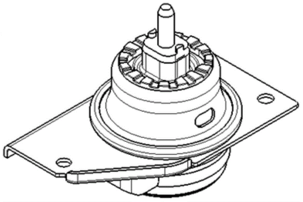
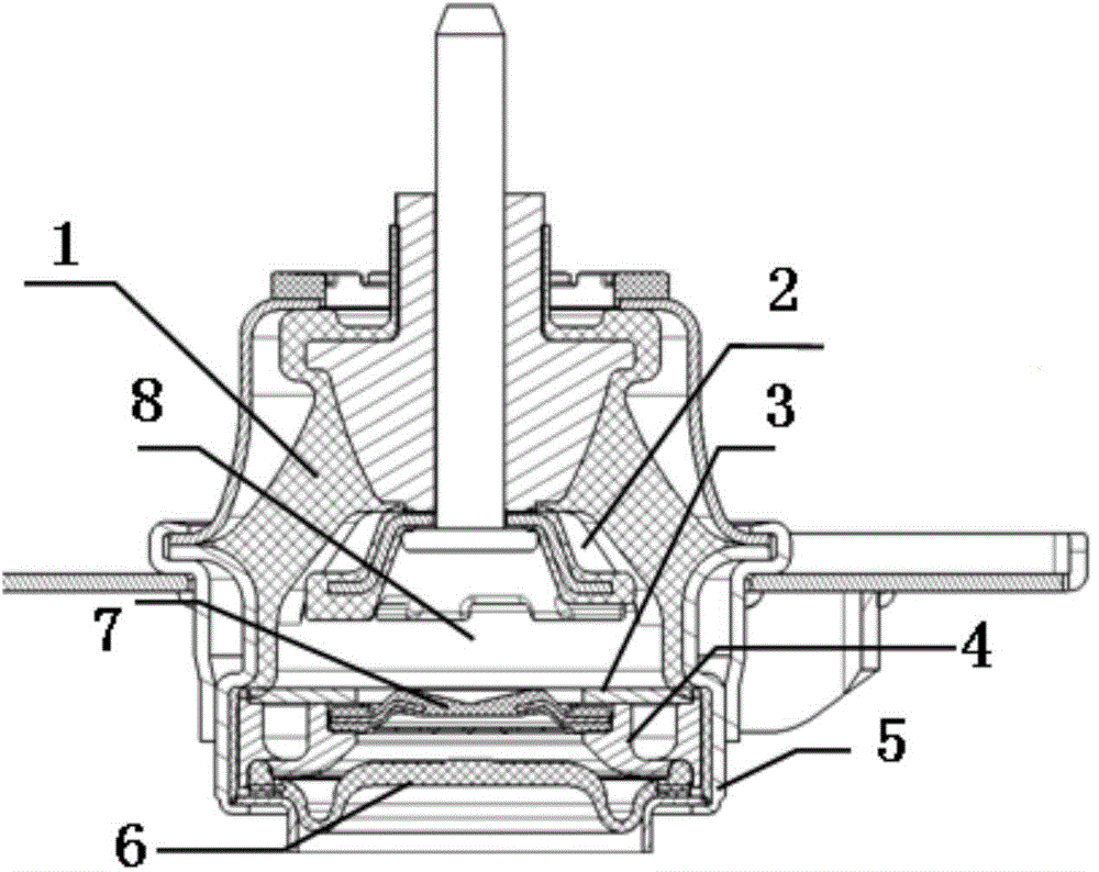
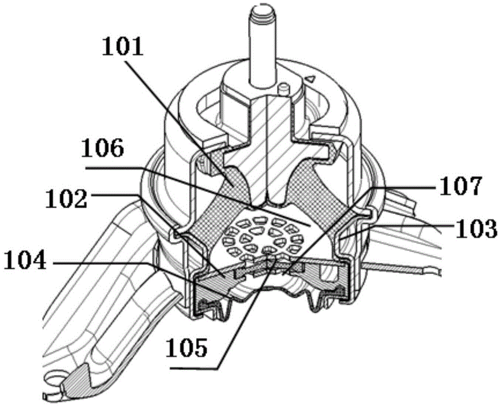
[0041] The invention provides a hydraulic mount, such as Figure 3 to Figure 7 As shown, it includes main spring 101, flow channel 102, pressure plate 108, metal skeleton 103, bottom film 104, decoupling diaphragm 105, upper liquid chamber 106 and lower liquid chamber 107; in the present invention, main spring 101, The metal skeleton 103 and the base film 104 are existing technologies without improvement, and in this application, the installation positions of each component are the same as those of the existing hydraulic mount, therefore, no detailed description will be given on these components and installation structures. description...


PUM


Abstract

The invention relates to a hydraulic suspension, which comprises a main spring, a flow passage, a platen, a metal skeleton, a bottom film, a decoupling membrane, an upper hydraulic chamber and a lower hydraulic chamber, wherein a plurality of through holes are formed in the places, which are opposite to the decoupling membrane, of the platen; a plurality of openings are formed in the places, which are opposite to the decoupling membrane, of the flow passage; a connecting line between the center of each opening and the center of through hole opposite to the opening is perpendicular to the decoupling membrane; the decoupling membrane is provided with bulges which outwards extend from the upper surface and the lower surface at the same time; the bugles are not opposite to the through holes. The through holes in the platen and in the flow passage are enabled to form a net structure; meanwhile, the bulges are added on the decoupling membrane to fix the decoupling membrane; the decoupling membrane can be effectively prevented from a large deformation quantity when being strongly impacted; the reliability problem of the decoupling membrane is solved.

Description

technical field [0001] The invention belongs to the field of automobile suspension, and specifically refers to a hydraulic suspension. Background technique [0002] For engine side mounts, in order to improve its vibration isolation performance at high frequencies, they are generally designed as hydraulic mounts. The main performance parameters of hydraulic mounts include dynamic-to-static ratio, dynamic stiffness at high frequencies, and large damping at low frequencies. Wait. Generally speaking, it is the stiffness of the decoupling diaphragm that affects the dynamic-to-static ratio, and it is the spoiler that affects the dynamic stiffness at high frequencies. Therefore, choosing a low-stiffness decoupling diaphragm is conducive to obtaining a smaller dynamic-to-static ratio and is conducive to isolating high-frequency and small-amplitude vibrations. However, the general low-stiffness decoupling diaphragm has low durability, especially for off-road vehicles, the road con...

Claims


Application Information

Patent Timeline
IPC IPC(8): F16F13/00
CPCF16F13/06
Inventor 彭宜爱胡俊生王方
Owner ANHUI JIANGHUAI AUTOMOBILE GRP CORP LTD
Why Eureka
Try Eureka