A sewage sludge separator

A sewage sludge and separator technology, applied in the direction of water/sewage multi-stage treatment, water/sludge/sewage treatment, chemical instruments and methods, etc., can solve the problems of reducing sludge and sewage treatment rate, surrounding environmental pollution, purchasing To solve the problem of high cost, achieve the effect of simple structure, reduce labor cost and improve work efficiency

Active Publication Date: 2016-09-21
安徽省通源环境节能股份有限公司
View PDF4 Cites 1 Cited by
  • Summary
  • Abstract
  • Description
  • Claims
  • Application Information

AI Technical Summary

Problems solved by technology

[0002] At present, the special treatment equipment for industrial and urban environmental protection sludge sewage is generally complex in structure and expensive to purchase, and the treatment equipment will inevitably bring a certain amount of energy consumption, which brings considerable financial pressure to small-scale enterprises. Environmental protection departments or industrial enterprises, even if there is a sludge sewage treatment plan, are often discouraged due to insufficient funds, which reduces the sludge sewage treatment rate and causes huge environmental pollution to the surrounding environment

Method used


Image

  • A sewage sludge separator

Examples


Embodiment Construction

[0018] The following will make a clear and complete description of the sewage sludge separator of the present invention in conjunction with the accompanying drawings.

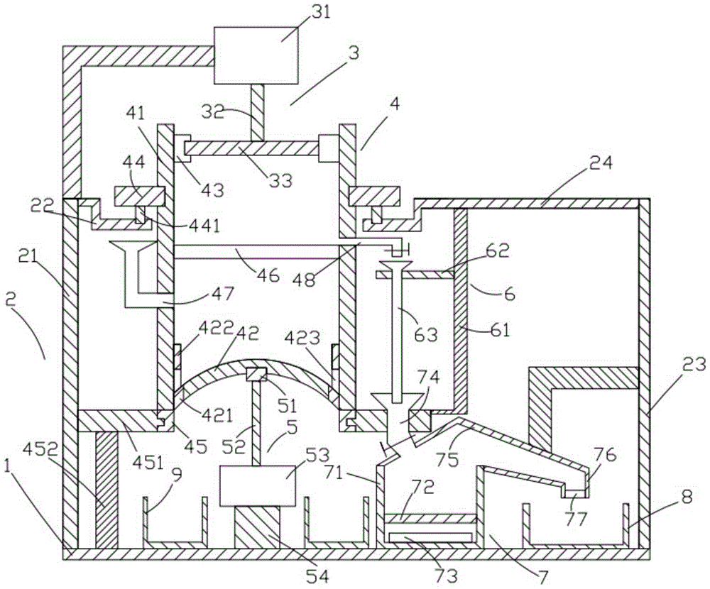
[0019] Such as figure 1 As shown, the sewage sludge separator of the present invention includes a base 1, a support device 2 located above the base 1, a rotating device 3 located above the support device 2, a frame device 4 located below the rotating device 3, The cylinder device 5 located below the frame device 4, the recovery device 6 located on the right side of the frame device 4, the heating device 7 located below the recovery device 6, the sewage recovery device located on the right side of the heating device 7 box 8 and the sludge recovery box 9 located on the left side of the heating device 7 .

[0020] Such as figure 1 As shown, the base 1 is in the shape of a cuboid, and the base 1 is placed horizontally. The support device 2 includes a first support column 21, a first support column 22 on the righ...


PUM


Abstract

A sewage and sludge separator comprises a base, a support device, a rotating device, a frame body device, a cylinder device, a recovery device, a heating device, a sewage recycle bin and a sludge recycle bin, wherein the support device comprises a first supporting column, a first support rod, a second supporting column and a second support rod; the rotating device comprises a motor, a first support, a first rotating shaft and a rotating rod; the frame body device comprises a frame body, a lower wall, a bulge, rolling wheels, a support ring, a filter screen, a feeding pipe and a water outlet pipe; the cylinder device comprises a support block, a cylinder, a propping rod and a cylindrical part; the recovery device comprises an L-shaped rod, a horizontal rod and a conveying pipe; the heating device comprises a heating frame, a heat-conducting plate, a heating rod, a cover body, a water inlet pipe, an outlet, a filtrating block and a second support; the lower wall is a upwards convex hemisphere; an enclosed ring is arranged on the side surface of the lower wall; the inner surface of the enclosed ring is fixedly connected with the side surface of the lower wall. The sewage and sludge separator can effectively separate sludge from sewage, and is high in separating efficiency and good in separating effect.

Description

technical field [0001] The invention relates to the technical field of environmental protection, in particular to a sewage sludge separator. Background technique [0002] At present, the special treatment equipment for industrial and urban environmental protection sludge sewage is generally complex in structure and expensive to purchase, and the treatment equipment will inevitably bring a certain amount of energy consumption, which brings considerable financial pressure to small-scale enterprises. Environmental protection departments or industrial enterprises, even if they have a sludge sewage treatment plan, are often discouraged due to insufficient funds, which reduces the sludge sewage treatment rate and causes huge environmental pollution to the surrounding environment. . [0003] Therefore, it is necessary to provide a new technical solution to overcome the above defects. Contents of the invention [0004] The object of the present invention is to provide a sewage s...

Claims


Application Information

Patent Timeline
Patent Type & Authority Patents(China)
IPC IPC(8): C02F9/10
Inventor 杨明程俊张娜王啟华汪邦春方志华汪国成陈红刘帮樑
Owner 安徽省通源环境节能股份有限公司
Why Eureka
Try Eureka