Arrangement for a fuel injection system with a fuel injection valve and a decoupling element

A technology of fuel injection valves and components, applied in the field of decoupling components, to achieve the effects of improving vibration damping, reducing noise transmission, and high noise damping

Active Publication Date: 2015-07-22
ROBERT BOSCH GMBH
View PDF5 Cites 4 Cited by
  • Summary
  • Abstract
  • Description
  • Claims
  • Application Information

AI Technical Summary

Problems solved by technology

[0005] The decoupling element known from DE 10 2008 054 591 A1 has the disadvantage that the decoupling element is configured as a disk spring and is tensioned in the assembled state
Therefore, the problem arises over the service life of ensuring sufficient structural strength and at the same time ensuring the desired noise reduction

Method used


Image

  • Arrangement for a fuel injection system with a fuel injection valve and a decoupling element
  • Arrangement for a fuel injection system with a fuel injection valve and a decoupling element
  • Arrangement for a fuel injection system with a fuel injection valve and a decoupling element

Examples


Embodiment Construction

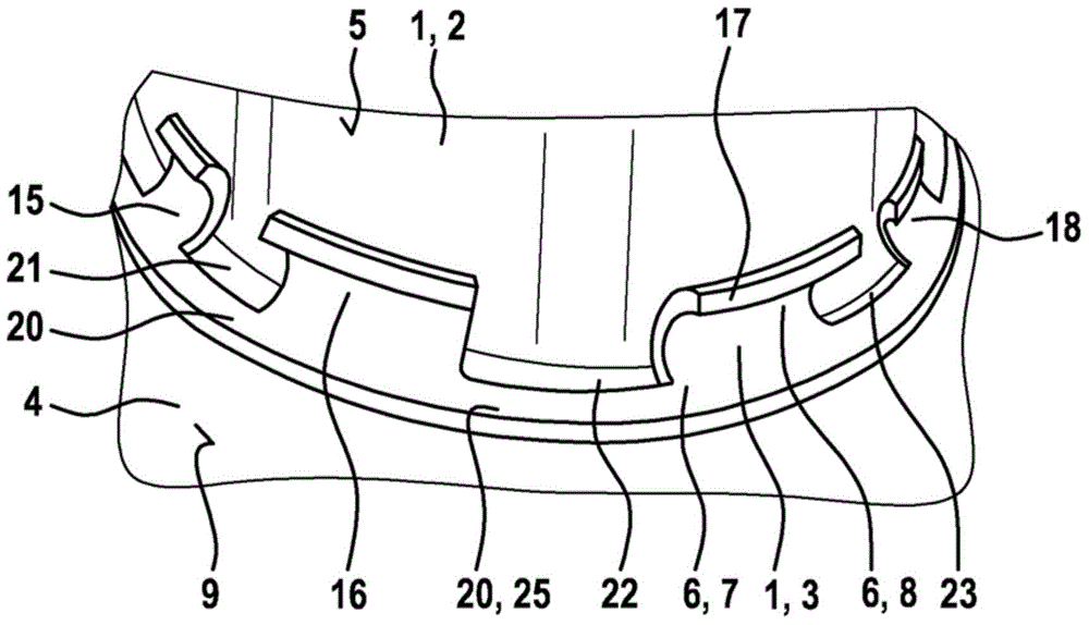
[0027] figure 1 Arrangement 1 with fuel injection valve 2 and decoupling element 3 and cylinder head 4 according to the first exemplary embodiment of the invention are shown in a simplified, schematic and three-dimensional illustration. The arrangement 1 is for a fuel injection system of an internal combustion engine. The arrangement 1 is particularly suitable here for a fuel injection system for injecting fuel directly into a combustion chamber of an internal combustion engine. The internal combustion engine can be designed in particular as a mixture-compressing, spark-ignition internal combustion engine, gasoline or other fuels suitable for such internal combustion engines and suitable mixtures thereof being injected.

[0028] The decoupling element 3 is particularly suitable for this application.

[0029]The transmission of noise from fuel injection valve 2 to cylinder head 4 can be reduced by arranging assembly 1 or decoupling device 3 . Fuel injector 2 is designed, for...


PUM


Abstract

A decoupling element (3) serves to decouple a fuel injection valve (2) from a cylinder head. The decoupling element (3) has a main body (6) which serves to enclose a housing (5) of the fuel injection valve (2) in the assembled state. Here, a cylinder-side support region (7) which serves for supporting on the cylinder head (4) is formed on the main body (6). Furthermore, a valve-side supporting region (8) which serves for supporting the fuel injection valve (2) is formed on the main body (6). When the fuel injection valve (2) is supported between the valve-side supporting region (8) and the cylinder-side support region (7), the main body (6) is subjected to a compressive load. Here, only the cylinder-side support region (7) of the main body (6) is configured in the form of a closed ring, whereas the main body (6) has segments (15-18) which are distributed over a circumference and are connected to one another by the closed ring (20) of the cylinder-side support region (7). Here, the decoupling element (3) makes it possible to reduce the transmission of sound from the fuel injection valve (2) to the cylinder head (4). Furthermore, an arrangement (1) with a decoupling element (3) of this type and a fuel injection valve (2) is described.

Description

technical field [0001] The invention relates to a decoupling element for decoupling a fuel injection valve from a cylinder head and an arrangement having a fuel injection valve and the decoupling element. The invention relates in particular to the field of fuel injection systems for internal combustion engines, in which fuel under high pressure is injected into associated combustion chambers of the internal combustion engine via fuel injection valves. Background technique [0002] A compensating element for a fuel injection valve is known from DE 103 38 715 A1. In this case, the compensating element serves to mount the fuel injection valve in the cylinder head of the internal combustion engine. The compensating element is annular and is arranged between the valve housing of the fuel injector and the wall of the receiving bore of the cylinder head. The compensating element has arms which are supported on the fuel injection valve and the cylinder head. In this case, the fir...

Claims


Application Information

Patent Timeline
Patent Type & Authority Applications(China)
IPC IPC(8): F02M61/14
CPCF02M2200/26F02M2200/09F02M61/14F02M61/12F02M2200/8023
Inventor M·诺尔普M·迈尔M·舍费尔M·麦尔P·A·纳帕尔希门尼斯
Owner ROBERT BOSCH GMBH
Why Eureka
Try Eureka